Mitsubishi Montero (2004+). Manual - part 1141


  Index      Mitsubishi     Mitsubishi Montero - service repair manual 2004 year


Search            


Content   ..  1139  1140  1141  1142   ..


Mitsubishi Montero (2004+). Manual - part 1141


TOE CONTROL ARM ASSEMBLY AND TOE CONTROL TOWER BAR

TSB Revision

REAR SUSPENSION

34-23

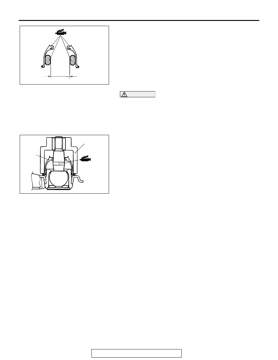
2. Apply multipurpose grease to the inside of the dust cover as 

shown. 

3. Apply multipurpose grease to the shown parts inside the 

dust cover and the ball joint stud.

4. Wrap plastic tape around the toe control arm ball joint stud, 

and then install the dust cover to the toe control arm ball 
joint. 

CAUTION

Do not apply grease to the place (tapered section) where 
the threaded section of the ball joint connects with the 
knuckle. Wipe the grease off if it is applied in this area. To 
prevent the grease from being applied to the ball joint con-
nection (taper) with the knuckle, do not compress the dust 
cover before installation. 
5. Using the special tool, drive the dust cover into the position 

shown in the illustration.

6. Press the dust cover with your finger to check that there are 

no cracks or damage in the dust cover.

ACX00726 AB

30 mm
(1.18 in) 
OR MORE

ACX00747AB

DUST 
COVER

MB990800

TRAILING ARM ASSEMBLY

TSB Revision

REAR SUSPENSION

34-24

TRAILING ARM ASSEMBLY

REMOVAL AND INSTALLATION

M1341004200103

CAUTION

*: Indicates parts which should be temporarily tightened, and then fully tightened with the vehicle on 
the ground in an unladen condition.

TRAILING ARM BUSHING REPLACEMENT

M1341011300113

Required Special Tool:

• MD998236: Output Shaft Bearing Installer

1. Use special tool MD998236 to drive in/out the bushing 

from/to the trailing arm.

Post-installation Operation
• Wheel Alignment Check and Adjustment (Refer to 

P.34-6

.)

ACX00748 AC

1

3

2

213 

± 34 N

·

m *

157 

± 25 ft-lb *

4

213 

± 34 N

·

m

157 

± 25 ft-lb

REMOVAL STEPS

1. TRAILING ARM TO KNUCKLE 

SECURING BOLT

2. TRAILING ARM TO REAR FRAME 

SECURING NUT

3. STOPPER
4. TRAILING ARM

REMOVAL STEPS (Continued)

ACX00749

MD998236

TRAILING ARM

AC

SPECIFICATIONS

TSB Revision

REAR SUSPENSION

34-25

2. When assembling, apply soapy water around the bushing 

and the inner diameter of the trailing arm, and then drive in 
the bushing so that it protrudes by the same amount at 
either side and its hollow part is as shown.

SPECIFICATIONS

FASTENER TIGHTENING SPECIFICATIONS

M1341012700233

ACX0750 AC

HOLLOW PART

ITEM

SPECIFICATION

Rear suspension assembly
Brake tube flare nut

15 

± 2 N⋅m (11 ± 2 ft-lb)

Crossmember mounting nut

167 

± 19 N⋅m (123 ± 14 ft-lb)

Nut securing lower arm to knuckle assembly

152 

± 25 N⋅m (113 ± 18 ft-lb)

Nut securing lower arm to body

123 

± 15 N⋅m (91 ± 11 ft-lb)

Nut securing shock absorber to lower arm assembly 152 

± 25 N⋅m (113 ± 18 ft-lb)

Nut securing trailing arm to rear frame

213 

± 34 N⋅m (157 ± 25 ft-lb)

Propeller shaft assembly nut

60 

± 10 N⋅m (45 ± 7 ft-lb)

Rear disc brake assembly mounting bolt

88 

± 10 N⋅m (65 ± 7 ft-lb)

Upper arm assembly
Brake pipe connection

15 

± 2 N⋅m (11 ± 2 ft-lb)

Nut securing upper arm assembly to rear frame

167 

± 10 N⋅m (124 ± 7 ft-lb)

Nut securing upper arm ball joint to knuckle

150 

± 30 N⋅m (111 ± 22 ft-lb)

Nut securing upper arm to upper arm ball joint 
assembly

98 

± 12 N⋅m (72 ± 9 ft-lb)

Stabilizer link mounting nut

104 

± 14 N⋅m (77 ± 10 ft-lb)

Shock absorber, coil spring and lower arm assembly
Nut securing lower arm to knuckle assembly

152 

± 25 N⋅m (113 ± 18 ft-lb)

Nut securing lower arm to body

123 

± 15 N⋅m (91 ± 11 ft-lb)

Nut securing shock absorber to lower arm assembly 152 

± 25 N⋅m (113 ± 18 ft-lb)

Shock absorber connecting nut

44 

± 10 N⋅m (33 ± 7 ft-lb)

Stabilizer bar
Stabilizer clamp mounting bolt

44 

± 10 N⋅m (33 ± 7 ft-lb)

Toe control arm assembly, toe control tower bar
Nut securing toe control arm ball joint to knuckle

67 

± 7 N⋅m (50 ± 5 ft-lb)

Nut securing toe control arm to rear frame

123 

± 15 N⋅m (91 ± 11 ft-lb)

Toe control tower bar mounting bolt, nut

46 

± 8 N⋅m (34 ± 6 ft-lb)

SPECIFICATIONS

TSB Revision

REAR SUSPENSION

34-26

GENERAL SPECIFICATIONS

M1341000200305

COIL SPRING

SERVICE SPECIFICATIONS

M1341000300272

Trailing arm assembly
Nut securing trailing arm to knuckle

213 

± 34 N⋅m (157 ± 25 ft-lb)

Nut securing trailing arm to rear frame

213 

± 34 N⋅m (157 ± 25 ft-lb)

ITEM

SPECIFICATION

ITEM

LS

except LS

Wire diameter mm (in)

18 

− 19 (0.71 − 0.75)

17 (0.67)

Average diameter mm (in)

133 

− 134 (5.24 − 5.28)

132 

− 134 (5.20 − 5.28)

Free length mm (in)

337 (13.3)

343 (13.5)

ITEM

SPECIFICATION

Toe-in mm (in)

± 3 (0.12 ± 0.12)

Camber

0

°00' ± 30' (Left/right deviation within 30')

Upper arm ball joint turning torque N

⋅m (in-lb)

1.5 

− 7.9 (13 − 70)

Stabilizer link ball joint turning torque N

⋅m (in-lb)

0.5 

− 2.0 (4 − 17)

Toe control arm ball joint turning torque N

⋅m (in-lb)

0.7 

− 1.0 (6 − 9)


Content   ..  1139  1140  1141  1142   ..