Mitsubishi Montero (2002-2004). Manual - part 758


  Index      Mitsubishi     Mitsubishi Montero - service repair manual 2002-2004 year


Search            


Content   ..  756  757  758  759   ..


Mitsubishi Montero (2002-2004). Manual - part 758


TSB Revision

SYMPTOM PROCEDURES

13Ad-81

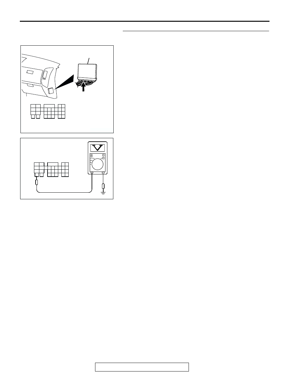
STEP 6. Measure the backup power supply voltage at PCM 
harness side connector D-133.
(1) Disconnect the connector D-133 and measure at the 

harness side.

(2) Measure the voltage between terminal No.58 and ground.

• Voltage should be battery positive voltage.

Q: Is battery positive voltage (approximately 12 volts) 

present?
YES : 
Go to Step 7.
NO :  Check harness connector A-03 at intermediate 

connector for damage, and repair or replace as 
required. Refer to GROUP 00E, Harness Connector 
Inspection 

P.00E-2

. If intermediate connector A-03 is 

in good condition, repair an open circuit between 
fusible link (5) and PCM connector D-133 (terminal 
No. 58). Then confirm that the malfunction symptom 
is eliminated.

AK200939

31

32

33

34

35

36

37

38

39

40

41

42

43

44

45

46

47

48

49

52

53

54

55

56

57

58

50

51

AB

CONNECTOR: D-133

HARNESS CONNECTOR: 
COMPONENT SIDE

PCM

D-133(GR)

AK201376

31

32

33

34

35

36

37

38

39

40

41

42

43

44

45

46

47

48

49

52

53

54

55

56

57

58

50

51

D-133 HARNESS 
CONNECTOR: 
COMPONENT SIDE

AK201376AB

31

32

33

34

35

36

37

38

39

40

41

42

43

44

45

46

47

48

49

52

53

54

55

56

57

58

50

51

TSB Revision

SYMPTOM PROCEDURES

13Ad-82

STEP 7. Check the continuity at PCM harness side 
connector D-133.
(1) Disconnect the connector D-133 and measure at the 

harness side.

(2) Check for the continuity between terminal No. 33, No. 42 

and ground.

• Should be less than 2 ohms.

Q: Is the continuity normal?

YES : Go to Step 8.
NO :  Check harness connector D-14 at intermediate 

connector for damage, and repair or replace as 
required. Refer to GROUP 00E, Harness Connector 
Inspection 

P.00E-2

. If intermediate connector D-14 is 

in good condition, repair an open circuit or harness 
damage between PCM connector D-133 (terminal No. 
33, No. 42) and ground. Then confirm that the 
malfunction symptom is eliminated.

AK200939

31

32

33

34

35

36

37

38

39

40

41

42

43

44

45

46

47

48

49

52

53

54

55

56

57

58

50

51

AB

CONNECTOR: D-133

HARNESS CONNECTOR: 
COMPONENT SIDE

PCM

D-133(GR)

31

32

33

34

35

36

37

38

39

40

41

42

43

44

45

46

47

48

49

52

53

54

55

56

57

58

50

51

AK201377

D-133 HARNESS 

CONNECTOR: 

COMPONENT SIDE

AK201377AB

TSB Revision

SYMPTOM PROCEDURES

13Ad-83

STEP 8. Measure the power supply voltage at PCM harness 
side connector D-133.
(1) Disconnect the connector D-133 and measure at the 

harness side.

(2) Measure the voltage between terminal No.57 and ground.

• Voltage should be battery positive voltage.

Q: Is battery positive voltage (approximately 12 volts) 

present?
YES : 
Go to Step 9.
NO :  Repair an open circuit between MFI relay connector 

B-22X (terminal No. 4) and PCM connector D-133 
(terminal No. 57). Then confirm that the malfunction 
symptom is eliminated.

AK200939

31

32

33

34

35

36

37

38

39

40

41

42

43

44

45

46

47

48

49

52

53

54

55

56

57

58

50

51

AB

CONNECTOR: D-133

HARNESS CONNECTOR: 
COMPONENT SIDE

PCM

D-133(GR)

AK201378

31

32

33

34

35

36

37

38

39

40

41

42

43

44

45

46

47

48

49

52

53

54

55

56

57

58

50

51

D-133 HARNESS 
CONNECTOR: 
COMPONENT SIDE

AK201378AB

31

32

33

34

35

36

37

38

39

40

41

42

43

44

45

46

47

48

49

52

53

54

55

56

57

58

50

51

TSB Revision

SYMPTOM PROCEDURES

13Ad-84

STEP 9. Measure the power supply voltage at PCM harness 
side connector D-133.
(1) Disconnect the connector D-133 and measure at the 

harness side.

(2) Using a jumper wire, connect terminal No. 57 to ground.

(3) Measure the voltage between terminal No. 34, No. 43 and 

ground.

• Voltage should be battery positive voltage.

Q: Is battery positive voltage (approximately 12 volts) 

present?
YES : 
Replace the PCM. Then confirm that the malfunction 

symptom is eliminated.

NO :  Check harness connector D-116 at intermediate 

connector for damage, and repair or replace as 
required. Refer to GROUP 00E, Harness Connector 
Inspection 

P.00E-2

If intermediate connector D-116 

is in good condition, repair an open circuit between 
MFI relay connector B-22X (terminal No. 1) and PCM 
connector D-133 (terminal No. 34, No. 43). Then 
confirm that the malfunction symptom is eliminated.

AK200939

31

32

33

34

35

36

37

38

39

40

41

42

43

44

45

46

47

48

49

52

53

54

55

56

57

58

50

51

AB

CONNECTOR: D-133

HARNESS CONNECTOR: 
COMPONENT SIDE

PCM

D-133(GR)

AK201379

31

32

33

34

35

36

37

38

39

40

41

42

43

44

45

46

47

48

49

52

53

54

55

56

57

58

50

51

D-133 HARNESS CONNECTOR: 
COMPONENT SIDE

AK201379AB

31

32

33

34

35

36

37

38

39

40

41

42

43

44

45

46

47

48

49

52

53

54

55

56

57

58

50

51


Content   ..  756  757  758  759   ..