Mitsubishi Montero (2002-2004). Manual - part 759


  Index      Mitsubishi     Mitsubishi Montero - service repair manual 2002-2004 year


Search            


Content   ..  757  758  759  760   ..


Mitsubishi Montero (2002-2004). Manual - part 759


TSB Revision

SYMPTOM PROCEDURES

13Ad-85

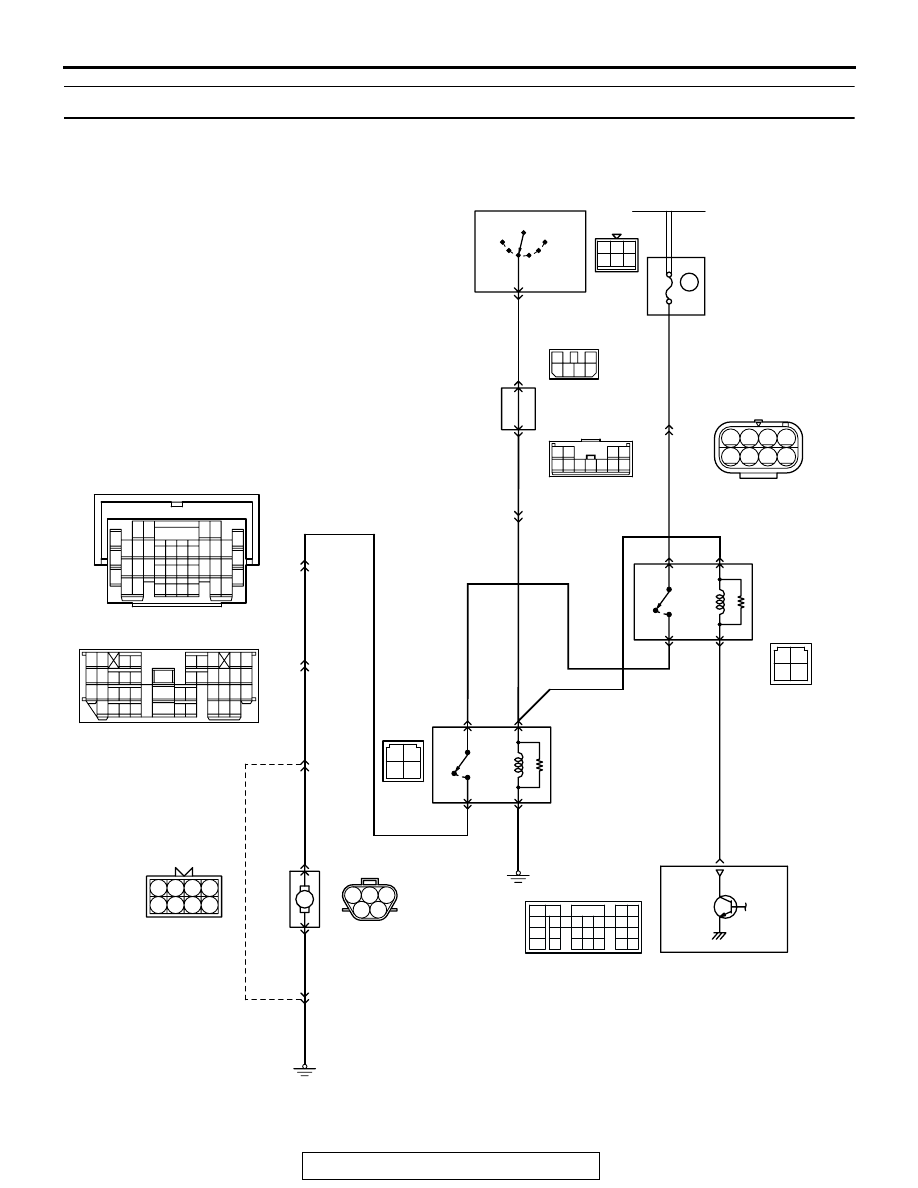
INSPECTION PROCEDURE 29: Fuel pump system.

M

BLUE-

BLA

CK

AK201158

BLA

CK

BLA

CK

BLA

CK-BLUE

BLA

CK-BLUE

BLUE-GREEN

BLA

CK

BLUE-

BLA

CK

RED-

WHITE

BLUE-

BLA

CK

BLA

CK-BLUE

BLA

CK-BLUE

BLA

CK-BLUE

BLA

CK-BLUE

BLA

CK-BLUE

3 4

1 2

B-24X

3 4

1 2

B-19X

FUEL PUMP
RELAY 2

FUEL PUMP
RELAY 1

POWERTRAIN
CONTROL
MODULE (PCM)

4

1

5

17

2

3

16

4

3

4 5

1 2 3

G-04

(MU802058)

8

R

IG2

ST

LOCK

ACC

IG1

2

IGNITION
SWITCH-IG

5

2

4

17

1

12 13 14

18

30

41

34

3

16

10

6 7

19

31

42

20

32

43

21

33

25

24

26

36

35

37

29

28

15

27

38

8 9

39 40

11

2

22

5

23

D-111

38

4

3

5

4

2

1

3

4 5 6

1 2

D-204

3

2

4 5 6

1

D-208

MU801331

9

6

10

17

18

29

2

3 4

7 8

19 20

30 31

12

11

24

33 34 35

21

32

27

26

36 37

28

38

25

13

15

14

16

23

22

1

5

E-111

E-111

E-111

7

9

1

3

6

11

2

4

8

5

10

D-221

(MU801866)

A-05

(MU802749)

8

7

6

5

1 2 3 4

F-07

MU802609

FUEL
PUMP

Fuel Pump Circuit

1

2

3

5

6 7 8 9

4

20

21 22

232425

2627

10111213

14 15

16 1718

19

D-132

(MU803802)

FUSIBLE
LINK(1)

6

20A

RELAY 
BOX

1

2 3

5

6 7

4

8

TSB Revision

SYMPTOM PROCEDURES

13Ad-86

.

AK201553

1

2

3

4

5

G-04(GR)

AB

CONNECTOR: G-04

HARNESS 
CONNECTOR: 
COMPONENT SIDE

AK201038

CONNECTOR: D-132

AB

PCM

D-132(GR)

AK201041AD

CONNECTOR: D-208

D-208

AK201176

B-19X

B-24X

AB

CONNECTORS: B-19X, B-24X

FUEL PUMP 
RELAY (1)

FUEL PUMP 
RELAY (2)

AK201045

D-204

AB

CONNECTOR: D-204

AK201294

D-221

AB

CONNECTOR: D-221

AK201060

E-111

AB

CONNECTOR: E-111

AK201055

CONNECTOR: D-111

D-111

AB

AK201054

F-07(B)

AB

CONNECTOR: F-07

AK201351

A-05(B)

AB

CONNECTOR: A-05

TSB Revision

SYMPTOM PROCEDURES

13Ad-87

CIRCUIT OPERATION

• Battery positive voltage is applied to the fuel 

pump relay 2 (terminal No. 4) from the ignition 
switch-IG.
Ground is provided through (terminal No. 2) to 
chassis ground.

• When the ignition switch is turned to the "ON" 

position, the fuel pump relay 2 turns ON.

• A battery positive voltage is applied on the fuel 

pump relay 1 (terminal No. 2) from the ignition 
switch-IG.

• During cranking and while the engine is running, 

the PCM turns the power transistor in the PCM 
ON to ground the fuel pump relay 1 coil. With this, 
the fuel pump relay 1 turns ON, and the battery 
positive voltage is supplied to the fuel pump from 
the fuel pump relay 1 (terminal No. 1), via fuel 
pump relay 2.

.

TROUBLESHOOTING HINTS (The most likely 
causes for this code to be set are: ) 

• Malfunction of the fuel pump relay.

• Malfunction of the fuel pump.

• Improper connector contact, open or short-

circuited harness wire.

• Malfunction of the PCM.

DIAGNOSIS

Required Special Tool:

• MB991502: Scan Tool (MUT-II)

STEP 1. Using scan tool MB991502, check actuator test 
item 07: Fuel Pump.

CAUTION

To prevent damage to scan tool MB991502, always turn the 
ignition switch to the "LOCK" (OFF) position before con-
necting or disconnecting scan tool MB991502.
(1) Connect scan tool MB991502 to the data link connector.
(2) Turn the ignition switch to the "ON" position.
(3) Set scan tool MB991502 to the actuator test mode for item 

07, Fuel Pump.

• An operation sound of the fuel pump should be heard.

(4) Turn the ignition switch to the "LOCK" (OFF) position.
Q: Is the fuel pump operating properly?

YES : That this malfunction is intermittent. Refer to GROUP 

00, How to Use Troubleshooting/Inspection Service 
Points 

P.00-6

NO :  Go to Step 2.

STEP 2. Check connector B-19X at fuel pump relay 1 and 
connector B-24X at fuel pump relay 2 for damage.
Q: Is the connector in good condition?

YES : Go to Step 3.
NO :  Repair or replace it. Refer to GROUP 00E, Harness 

Connector Inspection 

P.00E-2

. Then confirm that the 

malfunction symptom is eliminated.

ACX01539

16-PIN

MB991502

AC

AK201178

2 1

3

4

B-19X

B-24X

AB

CONNECTORS: B-19X, B-24X

HARNESS 
CONNECTOR: 
COMPONENT SIDE

TSB Revision

SYMPTOM PROCEDURES

13Ad-88

STEP 3. Check the fuel pump relay 1 and 2.
(1) Remove the fuel pump relay.

(2) Check for continuity between the fuel pump relay terminal 

No. 2 and No. 4.

• There should be continuity. (approximately 70 ohms)

(3) Use jumper wires to connect fuel pump relay terminal No. 4 

to the positive battery terminal and terminal No. 2 to the 
negative battery terminal.

(4) Check for continuity between the fuel pump relay terminal 

No. 1 and No. 3 while connecting and disconnecting the 
jumper wire at the negative battery terminal.

• Should be less than 2 ohms. (Negative battery terminal 

connected)

• Should be open loop. (Negative battery terminal discon-

nected)

(5)  Install the fuel pump relay.
Q: Is the resistance normal?

YES : Go to Step 4.
NO :  Replace the fuel pump relay. Then confirm that the 

malfunction symptom is eliminated.

AK201178

2 1

3

4

B-19X

B-24X

AB

CONNECTORS: B-19X, B-24X

HARNESS 
CONNECTOR: 
COMPONENT SIDE

1

2

3

4

AK201380

FUEL PUMP
RELAY SIDE
CONNECTOR

AK201380AB

1

2

3

4

AK201381

FUEL PUMP
RELAY SIDE
CONNECTOR

AK201381AB


Content   ..  757  758  759  760   ..