Mitsubishi Montero (2002-2004). Manual - part 756


  Index      Mitsubishi     Mitsubishi Montero - service repair manual 2002-2004 year


Search            


Content   ..  754  755  756  757   ..


Mitsubishi Montero (2002-2004). Manual - part 756


TSB Revision

SYMPTOM PROCEDURES

13Ad-73

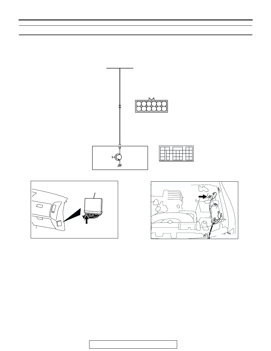
INSPECTION PROCEDURE 27: A/C condenser fan is inoperative

.

CIRCUIT OPERATION

• The battery positive voltage is applied on the 

PCM (terminal No. 17) from the condenser fan 
motor relay.

• When the PCM switches on its power transistor, 

the condenser fan motor relay coil is energized, 
causing current to flow in the circuit.

.

TROUBLESHOOTING HINTS (The most likely 
causes for this code to be set are: ) 

• Malfunction of the condenser fan motor relay.

• Malfunction of the condenser fan motor.

• Improper connector contact, open or short-

circuited harness wire.

• PCM failed. 

AK201156

LIGHT GREEN-

RED

LIGHT GREEN-

RED

17

3 4

8

6

5

11

10

12

9

7

1 2

A-03

(MU802611)

11

POWERTRAIN
CONTROL
MODULE (PCM)

CONDENSER FAN
RELAY

A/C Condenser Fan Circuit

1

2

3

5

6 7 8 9

4

20

21 22

232425

2627

10111213

14 15

16 1718

19

D-132

(MU803802)

AK201038

CONNECTOR: D-132

AB

PCM

D-132(GR)

AK201046

A-03(B)

AB

CONNECTOR: A-03

TSB Revision

SYMPTOM PROCEDURES

13Ad-74

DIAGNOSIS

STEP 1. Check harness connector D-132 at PCM for 
damage.
Q: Is the harness connector in good condition?

YES :  Go to Step 2.
NO :  Repair or replace it. Refer to GROUP 00E, Harness 

Connector Inspection 

P.00E-2

. Then confirm that the 

malfunction symptom is eliminated.

STEP 2. Measure the output voltage at PCM harness side 
connector D-132.
(1) Disconnect the connector D-132 and measure at the 

harness side.

(2) Turn the ignition switch to the "ON" position.

(3) Measure the voltage between terminal No. 17 and ground.

• Voltage should be battery positive voltage.

(4) Check the condenser fan condition.

• When the terminal No. 17 is disconnected, the fan 

should stop.

• When the terminal No. 17 is grounded by the jumper 

cable, the fan should run.

(5) Turn the ignition switch to the "LOCK" (OFF) position.
Q: Is the voltage and fan condition normal?

YES :  Replace the PCM. Then confirm that the malfunction 

symptom is eliminated.

NO :  Refer to GROUP 55, Introduction To Heater, Air 

Conditioning And Ventilation Diagnosis 

P.55A-5

.

AK200938

2

3

4

5

6

7

8

9

1

10

14

15

16

17

18

19

20

21

22

23

24

25

26

27

11

12

13

AB

CONNECTOR: D-132

HARNESS CONNECTOR: 
COMPONENT SIDE

PCM

D-132(GR)

AK200938

2

3

4

5

6

7

8

9

1

10

14

15

16

17

18

19

20

21

22

23

24

25

26

27

11

12

13

AB

CONNECTOR: D-132

HARNESS CONNECTOR: 
COMPONENT SIDE

PCM

D-132(GR)

AK201374

2

3

4

5

6

7

8

9

1

10

14

15

16

17

18

19

20

21

22

23

24

25

26

27

11

12

13

D-132 HARNESS 
CONNECTOR: 
COMPONENT SIDE

AK201374AB

2

3

4

5

6

7

8

9

1

10

14

15

16

17

18

19

20

21

22

23

24

25

26

27

11

12

13

TSB Revision

SYMPTOM PROCEDURES

13Ad-75

INSPECTION PROCEDURE 28: Power supply system and ignition switch-IG system.

WHITE-

BLA

CK

WHITE-

BLA

CK

WHITE-

BLA

CK

WHITE-

BLA

CK

BLA

CK

WHITE-BLA

CK

BLA

CK

AK201157

RED

WHITE-BLUE

RED

RED

BLUE-BLA

CK

BLUE-BLA

CK

BLUE-BLA

CK

1

6

7

4

1

3

5

4

2

3

2

4 5 6

1

D-208

MU801331

8

2

3

2

1

8

5 6 7

4

D-221

(MU801866)

R

IG2

ST

LOCK

ACC

IG1

3

4 5 6

1 2

D-204

2

IGNITION SWITCH

4

1 2
3

B-22X

2

POWERTRAIN
CONTROL
MODULE (PCM)

3

58

FUSIBLE
LINK (5)

5

57

34

50

POWER
SUPPLY

BATTERY
BACKUP

42

43

33

MFI RELAY

1
5

7 8

3 4
9 10

2
6

D-14

MU801335

1

12

23 24 25 26

2

13

3

14

4

15

5

16

6

17

7

18

8

19

9

20 21 22

27 28 29 30 31 32 33

10 11

D-116

9

6

10

17

18

29

2

3 4

7 8

19 20

30 31

12

11

24

33 34 35

21

32

27

26

36 37

28

38

25

13

15

14

16

23

22

1

5

E-111

Power Supply and Ignition Switch-IG Circuit

31

35363738394041 42 43
444546474849

50 51

5253

545556

57 58

32

33 34

D-133

(MU803803)

A-03

(MU802611)

1 2 3 4 5 6
7 8 9 10 11 12

TSB Revision

SYMPTOM PROCEDURES

13Ad-76

AK201038

CONNECTOR: D-133

AC

PCM

D-133(GR)

AK201045

D-204

AB

CONNECTOR: D-204

AK201041AD

CONNECTOR: D-208

D-208

AK201046

A-03(B)

AB

CONNECTOR: A-03

AK201039

MFI RELAY

B-22X

AB

CONNECTOR: B-22X

AK201049

CONNECTOR: D-116

D-116

AC

AK201294

D-221

AB

CONNECTOR: D-221

AK201043

E-111

AB

CONNECTOR: E-111

AK201049

D-14

AB

CONNECTOR: D-14


Content   ..  754  755  756  757   ..