Mitsubishi Montero (2002-2004). Manual - part 754


  Index      Mitsubishi     Mitsubishi Montero - service repair manual 2002-2004 year


Search            


Content   ..  752  753  754  755   ..


Mitsubishi Montero (2002-2004). Manual - part 754


TSB Revision

SYMPTOM PROCEDURES

13Ad-65

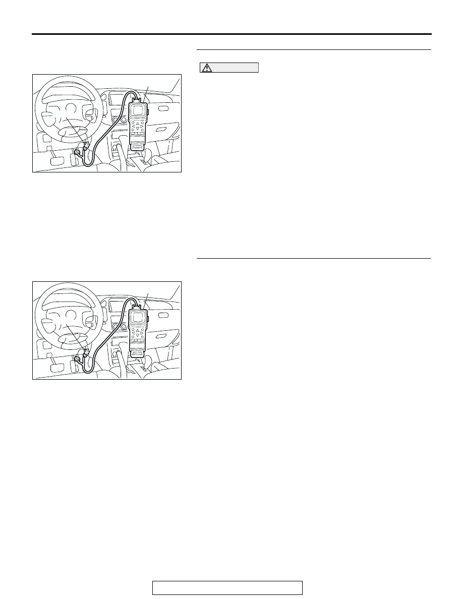
STEP 6. Using scan tool MB991502, check data list.

CAUTION

To prevent damage to scan tool MB991502, always turn the 
ignition switch to the "LOCK" (OFF) position before con-
necting or disconnecting scan tool MB991502.
(1) Connect scan tool MB991502 to the data link connector.
(2) Turn the ignition switch to the "ON" position.
(3) Check the following items in the data list. Refer to GROUP 

13A, Data List Reference Table 

P.13Ab-29

.

a. Item 21: Engine Coolant Temperature Sensor.
b. Item 13: Intake Air Temperature Sensor.

c. Item 25: Barometric pressure Sensor.

d. Item 69: Right Bank Heated Oxygen Sensor (rear).
e. Item 59: Left Bank Heated Oxygen Sensor (rear).

(4) Turn the ignition switch to the "LOCK" (OFF) position.
Q: Is the sensor operating properly?

YES : Go to Step 7.
NO :  Repair or replace. Then confirm that the malfunction 

symptom is eliminated.

STEP 7. Using scan tool MB991502, check data list item 39: 
Heated oxygen sensor bank 1, sensor 1 (right front).
(1) Start the engine and run at idle.
(2) Set scan tool MB991502 to the data reading mode for item 

39, Heated Oxygen Sensor bank 1, sensor 1 (right front).

• Warm up the engine. When the engine is decelerated 

suddenly from 4,000 r/min, the output voltage should 
increase from 200 millivolts or less to 600 

− 1,000 milli-

volts in a few seconds.

(3) Turn the ignition switch to the "LOCK" (OFF) position.
Q: Is the sensor operating properly?

YES : Go to Step 8.
NO :  Refer to GROUP 13A, DTC P0130 - Heated Oxygen 

Sensor Circuit (bank 1, sensor 1) 

P.13Ac-105

, DTC 

P0131 - Heated Oxygen Sensor Low Voltage (bank 1, 
sensor 1) 

P.13Ac-120

DTC P0132 - Heated Oxygen 

Sensor Circuit High Voltage (bank 1, sensor 1) 

P.13Ac-126

, DTC P0133 - Heated Oxygen Sensor 

Circuit Slow Response (bank 1, sensor 1) 

P.13Ac-

130

, DTC P0134 - Heated Oxygen Sensor Circuit No 

Activity Detected (bank 1, sensor 1) 

P.13Ac-133

.

ACX01539

16-PIN

MB991502

AC

ACX01539

16-PIN

MB991502

AC

TSB Revision

SYMPTOM PROCEDURES

13Ad-66

STEP 8. Using scan tool MB991502, check data list item 11: 
Heated oxygen sensor bank 2, sensor 1 (left front).
(1) Start the engine and run at idle.
(2) Set scan tool MB991502 to the data reading mode for item 

11, Heated Oxygen Sensor bank 2, sensor 1 (left front).

• Output voltage should be 0.6 − 1.0 volts when sudden 

revving.

(3) Turn the ignition switch to the "LOCK" (OFF) position.
Q: Is the sensor operating properly?

YES : Go to Step 9.
NO :  Refer to GROUP 13A, DTC P0150 - Heated Oxygen 

Sensor Circuit (bank 2, sensor 1) 

P.13Ac-189

, DTC 

P0151 - Heated Oxygen Sensor Circuit Low Voltage 
(bank 2, sensor 1) 

P.13Ac-204

, DTC P0152 - Heated 

Oxygen Sensor Circuit High Voltage (bank 2, sensor 
1) 

P.13Ac-210

, DTC P0153 - Heated Oxygen Sensor 

Circuit Slow Response (bank 2, sensor 1) 

P.13Ac-

214

, DTC P0154 - Heated Oxygen Sensor Circuit No 

Activity Detected (bank 2, sensor 1) 

P.13Ac-217

.

STEP 9. Using scan tool MB991502, check data list item 39: 
Heated oxygen sensor bank 1, sensor 1 (right front).
(1) Start the engine and run at idle.
(2) Set scan tool MB991502 to the data reading mode for item 

39, Heated Oxygen Sensor bank 1, sensor 1 (right front).

• Voltage should fluctuate between 0 − 0.4 volts and 0.6 − 

1.0 volts while after the engine has been warmed.

(3) Turn the ignition switch to the "LOCK" (OFF) position.
Q: Is the sensor operating properly?

YES : Go to Step 10.
NO :  Go to Step 12.

STEP 10. Check the EGR system.
Refer to GROUP 17, Emission Control System 

− General 

Description (EGR System) 

P.17-63

.

Q: Is the EGR system normal?

YES : Go to Step 11.
NO :  Repair or replace. Then confirm that the malfunction 

symptom is eliminated.

ACX01539

16-PIN

MB991502

AC

ACX01539

16-PIN

MB991502

AC

TSB Revision

SYMPTOM PROCEDURES

13Ad-67

STEP 11. Using scan tool MB991502, check data list item 
69: Heated oxygen sensor bank 1, sensor 2 (right rear).

CAUTION

To prevent damage to scan tool MB991502, always turn the 
ignition switch to the "LOCK" (OFF) position before con-
necting or disconnecting scan tool MB991502.
(1) Connect scan tool MB991502 to the data link connector.
(2) Start the engine and run at idle.
(3) Set scan tool MB991502 to the data reading mode for item 

69, Heated Oxygen Sensor bank 1, sensor 2 (right rear).

• Average voltage should be 0.6 volts or less, when idling.

(4) Turn the ignition switch to the "LOCK" (OFF) position.
Q: Is the sensor operating properly?

YES : Go to Step 16.
NO :  Replace the right bank heated oxygen sensor (front). 

Then confirm that the malfunction symptom is 
eliminated.

STEP 12. Using scan tool MB991502, check data list item 
11: Heated oxygen sensor bank 2, sensor 1 (left front).
(1) Start the engine and run at idle.
(2) Set scan tool MB991502 to the data reading mode for item 

11, Heated Oxygen Sensor bank 2, sensor 1 (left front).

• Warm up the engine. When the engine is decelerated 

suddenly from 4,000 r/min, the output voltage should 
increase from 200 millivolts or less to 600 

− 1,000 milli-

volts in a few seconds.

(3) Turn the ignition switch to the "LOCK" (OFF) position.
Q: Is the sensor operating properly?

YES : Go to Step 13.
NO :  Go to Step 15.

STEP 13. Check the EGR system.
Refer to GROUP 17, Emission Control System 

− General 

Description (EGR System) 

P.17-63

.

Q: Is the EGR system normal?

YES : Go to Step 14.
NO :  Repair or replace. Then confirm that the malfunction 

symptom is eliminated.

ACX01539

16-PIN

MB991502

AC

ACX01539

16-PIN

MB991502

AC

TSB Revision

SYMPTOM PROCEDURES

13Ad-68

STEP 14. Using scan tool MB991502, check data list item 
59: Heated oxygen sensor bank 2, sensor 2 (left rear).

CAUTION

To prevent damage to scan tool MB991502, always turn the 
ignition switch to the "LOCK" (OFF) position before con-
necting or disconnecting scan tool MB991502.
(1) Connect scan tool MB991502 to the data link connector.
(2) Start the engine and run at idle.
(3) Set scan tool MB991502 to the data reading mode for item 

59, Heated Oxygen Sensor bank 2, sensor 2 (left rear).

• Average voltage should be 0.6 volts or less, when idling.

(4) Turn the ignition switch to the "LOCK" (OFF) position.
Q: Is the sensor operating properly?

YES : Go to Step 16.
NO :  Replace the left bank heated oxygen sensor (front). 

Then confirm that the malfunction symptom is 
eliminated.

STEP 15. Check the fuel pressure.
Refer to GROUP 13A, On-vehicle Service 

− Fuel Pressure Test 

P.13Aa-13

.

Q: Is the fuel pressure normal?

YES : Go to Step 16.
NO :  Repair or replace. Then confirm that the malfunction 

symptom is eliminated.

STEP 16. Check the following items.
(1) Check the following items, and repair or replace the 

defective items.

a. Check the injectors for fuel leakage.
b. Check the ignition coil, spark plugs, spark plug cables.

c. Check compression pressure.

d. Check the positive crankcase ventilation system.
e. Check the evaporative emission system.

(2) Then check the malfunction symptom.
Q: Is the malfunction symptom is eliminated?

YES : The check is completed.
NO :  Replace the catalytic converter. Then confirm that the 

malfunction symptom is eliminated.

ACX01539

16-PIN

MB991502

AC


Content   ..  752  753  754  755   ..