Mitsubishi Montero (2002-2004). Manual - part 558
ON-VEHICLE SERVICE
TSB Revision
MULTIPORT FUEL INJECTION (MFI)
13Aa-19
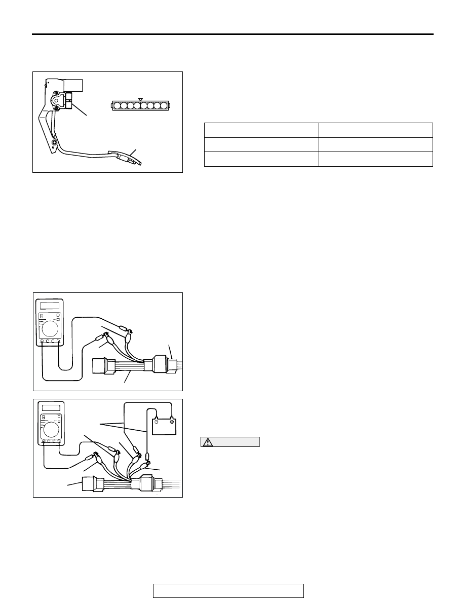
ACCELERATOR PEDAL POSITION SWITCH
CHECK
M1131052500012
.
1. Disconnect the accelerator pedal position sensor connector.
2. Check continuity between terminal No. 4 (accelerator pedal
position switch) and No. 5 (sensor earth) of the connector.
Normal condition:
3. If defective, replace the accelerator pedal position sensor
assembly.
NOTE: After replacement, adjust the accelerator pedal posi-
tion sensor. (Refer to
HEATED OXYGEN SENSOR CHECK
M1131005000323
Required Special Tools:
• MB991316: Test Harness Set
• MD998464: Test Harness
.
<Left bank heated oxygen sensor (front)>
1. Using scan tool MB991502, observe HO
2
S reading. If
values are unsatisfactory, or if a scan tool is not available,
use the following procedure:
(1) Disconnect the heated oxygen sensor connector and
connect special tool MB991316 to the connector on the
heated oxygen sensor side.
(2) Make sure that there is continuity [4.5-8.0 kiloohms at
20
°C (68°F)] between terminal No. 1 (red clip of special
tool) and terminal No. 3 (blue clip of special tool) on the
heated oxygen sensor connector
(3) If there is no continuity, replace the heated oxygen
sensor.
(4) Warm up the engine until engine coolant is 80
°C (176°F)
or higher.
CAUTION
Be very careful when connecting the jumper wires; incor-
rect connection can damage the heated oxygen sensor.
(5) Use the jumper wires to connect terminal No. 1 (red clip)
of the heated oxygen sensor connector to the positive
battery terminal and terminal No. 3 (blue clip) to the
negative battery terminal.
(6) Connect a digital voltage meter between terminal No. 2
(black clip) and terminal No. 4 (white clip).
2. While repeatedly revving the engine, measure the heated
oxygen sensor output voltage.
Accelerator pedal
Continuity
Depressed
No continuity
Released
Continuity (0 k
Ω)
1 2 3 4 5 6 7 8
AK201309 AC
Equipment side
connector
ACCELERATOR PEDAL
POSITION SWITCH
ACCELERATOR
PEDAL
AKX01624 AB
MB991316
HEATED
OXYGEN
SENSOR
EQUIPMENT
SIDE
CONNECTOR
BLUE
RED
AKX01625 AB
BLUE
JUMPER
WIRES
BLACK
RED
WHITE
MB991316