Mitsubishi Montero (2002-2004). Manual - part 557


  Index      Mitsubishi     Mitsubishi Montero - service repair manual 2002-2004 year


Search            


Content   ..  555  556  557  558   ..


Mitsubishi Montero (2002-2004). Manual - part 557


ON-VEHICLE SERVICE

TSB Revision

MULTIPORT FUEL INJECTION (MFI)

13Aa-15

(2) Squeeze the fuel supply line closed to confirm leak-down 

occurs from defective fuel pump check valve.

(3) If pressure continues to drop with both fuel lines 

squeezed closed, injector(s) are leaking.

14.Release residual pressure from the fuel pipe line. (Refer to 

P.13Aa-15

.)

WARNING

Cover the hose connection with shop towels to pre-
vent splash of fuel that could be caused by some 
residual pressure in the fuel pipe line.

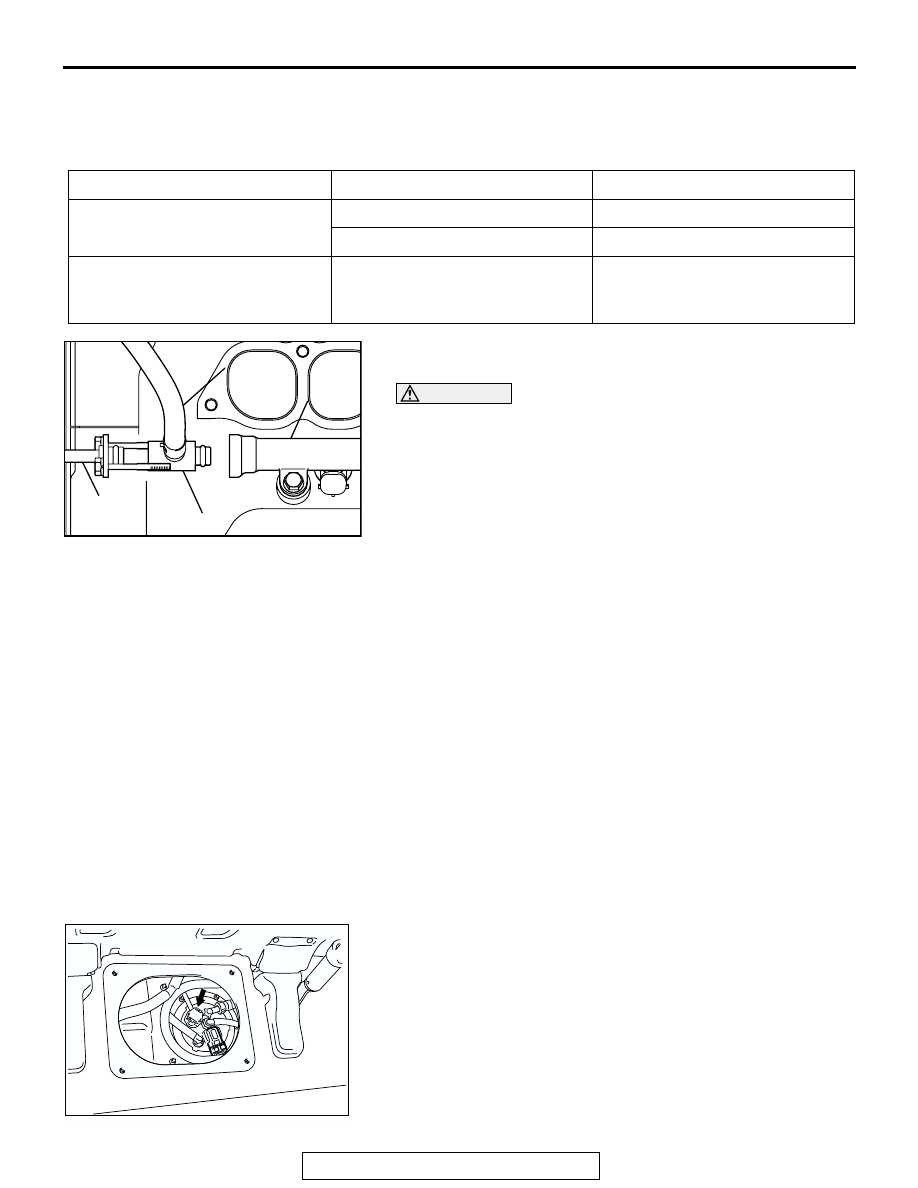
15.Remove the fuel pressure gauge, and special tools 

MD998709, MD998742 and MB991637 from the fuel rail.

16.Replace the O-ring at the end of the fuel high-pressure hose 

with a new one.

17.Fit the fuel high-pressure hose into the fuel rail and tighten 

the bolts to specified torque.

Tightening torque: 4.9 

± 1.0 Nm (43 ± 8 in-lb)

18.Check for fuel leaks.

(1) Use scan tool MB991502 to operate the fuel pump.
(2) Check the fuel line for leaks and repair as needed.

19.Disconnect scan tool MB991502.

FUEL PUMP CONNECTOR DISCONNECTION 
(HOW TO REDUCE PRESSURIZED FUEL LINES)

M1131000900451

When removing the fuel pipe, hose, etc., release fuel pressure 
to prevent fuel splay.
1. Turn the ignition switch to the "LOCK" (OFF) position.
2. Fold down the second seat.
3. Remove the service hole cover (upper) and packing.
4. Remove the service hole cover (lower) and packing.
5. Disconnect fuel pump module connector.
6. Start the engine and let it run until it stops naturally. Turn the 

ignition switch to the "LOCK" (OFF) position.

7. Connect the fuel pump module connector.

SYMPTOM

PROBABLE CAUSE

REMEDY

Fuel pressure drops gradually 
after engine is stopped

Leaky injector

Replace injector

Leaky fuel regulator valve seat

Replace fuel pressure regulator

Fuel pressure drops sharply 
immediately after engine is 
stopped

Check valve in fuel pump is held 
open

Replace fuel pump

AKX01460AB

MD998709

FUEL 
RAIL

MD998742

HIGH-
PRESSURE
FUEL HOSE

ACX00218 AM

ON-VEHICLE SERVICE

TSB Revision

MULTIPORT FUEL INJECTION (MFI)

13Aa-16

FUEL PUMP OPERATION CHECK

M1131002000476

Required Special Tool:
MB991502: Scan Tool (MUT-II)

CAUTION

To prevent damage to scan tool MB991502, always turn the 
ignition switch to the "LOCK" (OFF) position before con-
necting or disconnecting scan tool MB991502.
1. Check the operation of the fuel pump by using scan tool 

MB991502 (MUT-II) to force-drive the fuel pump.

2. If the fuel pump will not operate, check by using the 

following procedure, and if it is normal, check the drive 
circuit.

(1) Turn the ignition switch to the "LOCK" (OFF) position.

(2) Remove fuel pump relay (2). 

Connect terminal number 3 of the harness-side 
connector to the battery.
Check if the fuel pump operation sound can be heard at 
this time.
NOTE: As the fuel pump is an in-tank type, the fuel pump 
sound is hard to hear, so remove the fuel filler cap and 
check from the tank inlet.

(3) Check the fuel pressure by pinching the fuel hose with 

the fingertips.

(4) Install fuel pump relay (2).

MULTIPORT FUEL INJECTION (MFI) RELAY, 
THROTTLE ACTUATOR CONTROL MOTOR 
RELAY AND FUEL PUMP RELAY CONTINUITY 
CHECK

M1131052000017

ACX01543

MB991502

AB

16-PIN

AC203984

1

2

3

4

FUEL PUMP RELAY (2) 
HARNESS SIDE CONNECTOR

AB

BATTERY 
VOLTAGE

BATTERY POWER 
SUPPLY 
TERMINAL

SPECIFIED 
CONDITION

Supplied

2-4

1-3

Not supplied

2-4

1

2

3

4

AK201511AB

MFI RELAY SIDE
CONNECTOR

ON-VEHICLE SERVICE

TSB Revision

MULTIPORT FUEL INJECTION (MFI)

13Aa-17

INTAKE AIR TEMPERATURE SENSOR CHECK

M1131002800159

1. Disconnect the volume air flow sensor connectors.
2. Measure resistance between terminals 5 and 6.

Standard value:

13 

 17 k [at -20°C (-4°F)]

5.3 

 6.7 k [at 0°C (32°F)]

2.3 

 3.0 k [at 20°C (68°F)]

1.0 

 1.5 k [at 40°C (104°F)]

0.56 

 0.76 k [at 60°C (140°F)]

0.30 

 0.42 k [at 80°C (176°F)]

3. If not within specifications, replace the volume air flow 

sensor.

4. Measure resistance while heating the sensor using a hair 

dryer.

Normal condition:

5. If resistance does not decrease as heat increases, replace 

the volume air flow sensor assembly.

ENGINE COOLANT TEMPERATURE SENSOR 
CHECK

M1131003100153

CAUTION

Be careful not to touch the connector (resin section) with 
the tool when removing and installing.
1. Drain engine coolant, then remove the engine coolant 

temperature sensor.

2. With the temperature sensing portion of engine coolant 

temperature sensor immersed in hot water, check the 
resistance.

Standard value:

14 

 17 k [at -20°C (-4°F)]

5.1 

 6.5 k [at 0°C (32°F)]

2.1 

 2.7 k [at 20°C (68°F)]

0.9 

 1.3 k [at 40°C (104°F)]

0.48 

 0.68 k [at 60°C (140°F)]

0.26 

 0.36 k [at 80°C (176°F)]

3. If resistance deviates from the standard value greatly, 

replace the sensor.

4. Apply 3M

ä AAD part number 8731 or equivalent to threaded 

portion.

5. Install the engine coolant temperature sensor and tighten it 

to the specified torque.

Tightening torque: 29 

± 10 Nm (22 ± 7 ft-lb)

TEMPERATURE

RESISTANCE (k

)

Higher

Smaller

AKX01407AB

INTAKE AIR TEMPERATURE
SENSOR SIDE CONNECTOR

1 2 3 4 5 6 7

AKX01621 AB

INTAKE AIR
TEMPERATURE
SENSOR

AKX01622

AKX01623 AB

ON-VEHICLE SERVICE

TSB Revision

MULTIPORT FUEL INJECTION (MFI)

13Aa-18

THROTTLE POSITION SENSOR CHECK

M1131003200291

.

1. Disconnect the throttle position sensor connector.

2. Measure the resistance between the throttle position sensor 

side connector terminal No. 2 (sensor power supply) and 
terminal No. 4 (sensor ground).

Standard value: 2.0 

 4.0 kiloohms [at 20°C (68°F)]

3. If resistance is outside the standard value, replace the 

throttle body assembly.

ACCELERATOR PEDAL POSITION SENSOR 
CHECK

M1131003400024

.

1. Disconnect the accelerator pedal position sensor connector.
2. Measure the resistance between accelerator pedal position 

sensor connector terminal No. 1 [accelerator pedal position 
sensor (main) earth] and terminal No. 2 [accelerator pedal 
position sensor (main) power supply], and between terminal 
No.7 [accelerator pedal position sensor (sub) earth] and 
terminal No. 8 [accelerator pedal position sensor (sub) 
power supply].

Standard value: 3.5 

 6.5 kiloohms

3. Measure the resistance between accelerator pedal position 

sensor connector terminal No. 2 [accelerator pedal position 
sensor (main) power supply] and terminal No. 3 [accelerator 
pedal position sensor (main) output]; and between terminal 
No.8 [accelerator pedal position sensor (sub) power supply] 
and terminal No. 6 [accelerator pedal position sensor (sub) 
output].

Normal condition:

4. If the measured values are outside the standard value 

range, or if the resistance does not change smoothly, 
replace the accelerator pedal position sensor.
NOTE: After replacement, adjust the accelerator pedal posi-
tion sensor. (Refer to 

P.13Aa-12

.)

AK201173AE

THROTTLE 
POSITION 
SENSOR

6

1 2 3 4 5

AK201512

THROTTLE POSITION
SENSOR SIDE 
CONNECTOR

AB

When accelerator pedal 
is gently depressed

Changes comparatively smoothly 
in proportion to the accelerator 
pedal depression amount.

1 2 3 4 5 6 7 8

AK201309 AB

Equipment side
connector

ACCELERATOR PEDAL
POSITION SENSOR

ACCELERATOR 
PEDAL


Content   ..  555  556  557  558   ..