Mitsubishi Montero (2002-2004). Manual - part 556
ON-VEHICLE SERVICE
TSB Revision
MULTIPORT FUEL INJECTION (MFI)
13Aa-11
THROTTLE BODY CLEANING
M1131001000246
1. Start the engine and warm it up until the coolant is heated to
80
°C (176°F) or higher. Stop the engine.
2. Remove the air intake hose from the throttle body.
3. Spray cleaning solvent into the valve through the throttle
body intake port and leave it for approximately five minutes.
4. Start the engine, rev it several times and then idle it for about
one minute. If the idling speed becomes unstable (or if the
engine stalls) due to the bypass passage being plugged,
slightly open the throttle valve to keep the engine running.
5. If the throttle valve deposits are not removed, repeat steps 3
and 4.
6. Unplug the bypass passage inlet.
7. Attach the air intake hose.
8. Use scan tool MB991502 to erase any diagnostic trouble
code.
AK201059 AC
X
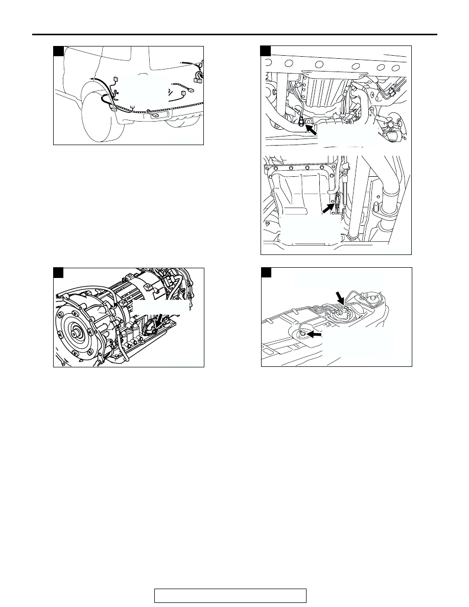
EVAPORATIVE
EMISSION
VENTILATION
SOLENOID
AK201275AC
RIGHT BANK
HEATED OXYGEN
SENSOR (REAR)
RIGHT BANK
HEATED OXYGEN
SENSOR (REAR)
CONNECTOR
Y
AK201288
TRANSMISSION
RANGE SWITCH
AC
Z
AK201308
FUEL SENSOR
(INCORPORATING
FUEL TEMPERATURE
SENSOR)
AB
a
FUEL TANK DIFFERENTIAL
PRESSURE SENSOR