Mitsubishi Montero (2002-2004). Manual - part 559


  Index      Mitsubishi     Mitsubishi Montero - service repair manual 2002-2004 year


Search            


Content   ..  557  558  559  560   ..


Mitsubishi Montero (2002-2004). Manual - part 559


ON-VEHICLE SERVICE

TSB Revision

MULTIPORT FUEL INJECTION (MFI)

13Aa-23

Standard value:

3. If the sensor is defective, replace the heated oxygen sensor.
NOTE: For removal and installation of the heated oxygen sen-
sor, refer to GROUP 15, Exhaust Pipe and Main Muffler 
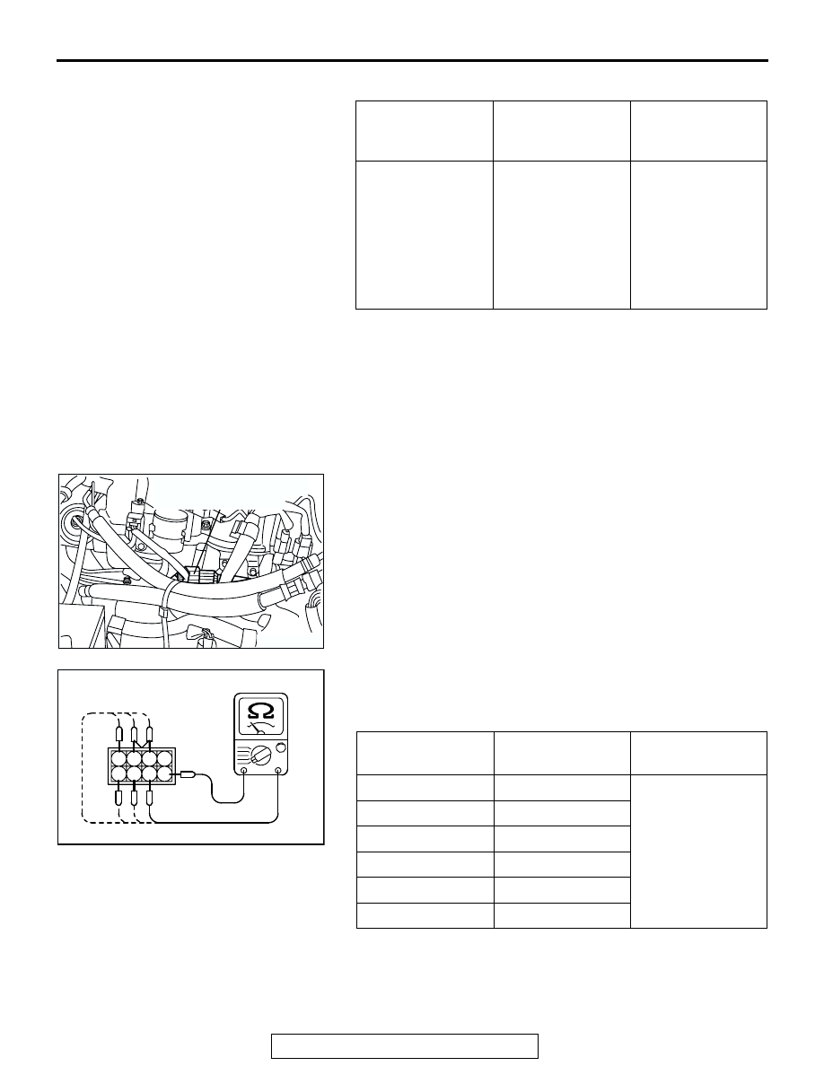
P.15-

13

.

INJECTOR CHECK

M1131005200219

Measurement of Resistance between Terminals

1. Disconnect the injector intermediate connector.

2. Measure the resistor between the injector intermediate male 

side connector terminals.

Standard value:

3. Connect the injector intermediate connector.

ENGINE

HEATED OXYGEN 
SENSOR OUTPUT 
VOLTAGE

REMARKS

When revving 
engine

0.6 

− 1.0 V

If you make the air/
fuel ratio rich by 
revving the engine 
repeatedly, a 
normal heated 
oxygen sensor will 
output a voltage of 
0.6 

− 1.0 V.

AK201314AB

INJECTOR INTERMEDIATE
HARNESS CONECTOR

INJECTOR NO.

MEASUREMENT 
TERMINAL

RESISTANCE

NO. 1

− 3

13 

− 16 kΩ

 [20

°C (68°F)]

NO. 2

− 2

NO. 3

− 1

NO. 4

− 7

NO. 5

− 6

NO. 6

− 5

AKX01494

INJECTOR INTERMEDIATE
MALE SIDE CONNECTOR

1 2 3 4

5 6 7 8

AB

ON-VEHICLE SERVICE

TSB Revision

MULTIPORT FUEL INJECTION (MFI)

13Aa-24

THROTTLE ACTUATOR CONTROL MOTOR 
CHECK

M1131051000014

.

<Operation Inspection>
1. Disconnect the air intake hose from the throttle body.
2. Set the ignition switch to the ON position.
3. Operate the accelerator pedal and confirm that the throttle 

valve is opening and closing accordingly.

.

<Checking the Terminal Resistance>
1. Disconnect the throttle position sensor connector.
2. Measure the resistance between terminal No. 5 and No. 6.

Standard value0.3 

 100 ohms [at 20°C (68°F)]

3. If resistance is outside the standard value, replace the 

throttle body assembly.

EVAPORATIVE EMISSION PURGE SOLENOID 
CHECK

M1131005600024

Refer to GROUP 17, Emission Control System 

− Evaporative 

Emission Control System 

− Evaporative Emission Purge Sole-

noid Check 

P.17-62

.

EGR VALVE CHECK

M1131051500019

Refer to GROUP 17, Emission Control System 

− Exhaust Gas 

Recirculation (EGR) System 

− EGR Valve Check.

P.17-64

INTAKE MANIFOLD TUNING SOLENOID CHECK

M1131006500031

Refer to GROUP 15, Intake and Exhaust System 

− On-vehicle 

Service 

− Intake Manifold Tuning Solenoid Check 

P.15-4

.

AK201173AC

THROTTLE 
ACTUATOR 
CONTROL 
MOTOR 

6

1 2 3 4 5

AK201513AB

THROTTLE ACTUATOR
CONTROL MOTOR
SIDE CONNECTOR

INJECTOR

TSB Revision

MULTIPORT FUEL INJECTION (MFI)

13Aa-25

INJECTOR

REMOVAL AND INSTALLATION

M1131007100434

Pre-removal Operation
• Fuel Line Pressure Reduction (Refer to 

P.13Aa-15

).

• Intake Manifold Plenum Removal (Refer to GROUP15 

P.15-7

).

Post-installation Operation
• Intake Manifold Plenum Installation (Refer to GROUP 15 

P.15-7

).

• Fuel Leakage Inspection

AC203985AB

9.0 ± 1.0 N

·

m

80 ± 9 in-lb

12 ± 1 N·m
102 ± 13 in-lb

8

4, 6, 15

3, 5, 14

11

9

16

ENGINE OIL

7

1

3

2

4

10

5

12

14

16

13

12

7

15

8

11

11

16

N

N

N

9.0 ± 1.0 N

·

m

80 ± 9 in-lb

N

6

N

5.0 ± 1.0 N·m
44 ± 9 in-lb

15

N

9

13

N

10

N

12 ± 1 N·m
102 ± 13 in-lb

12 ± 1 N·m
102 ± 13 in-lb

9

9

12

N

13

N

REMOVAL STEPS

1.

VACUUM HOSE

2.

FUEL RETURN HOSE 
CONNECTION

>>A<<

3.

FUEL PRESSURE REGULATOR

4.

O-RING

>>A<<

5.

FUEL HIGH-PRESSURE HOSE 
CONNECTION

6.

O-RING

7.

INJECTOR CONNECTORS

<<A>>

8.

FUEL INJECTORS, FUEL PIPE 
AND FUEL RAILS ASSEMBLY

9.

INSULATORS

10. INSULATORS

>>A<<

11. INJECTORS

REMOVAL STEPS (Continued)

INJECTOR

TSB Revision

MULTIPORT FUEL INJECTION (MFI)

13Aa-26

REMOVAL SERVICE POINT

.

<<A>> FUEL INJECTORS, FUEL PIPE AND FUEL RAILS 
ASSEMBLY REMOVAL

CAUTION

Do not drop the injector.

INSTALLATION SERVICE POINT

.

>>A<< FUEL PIPE/INJECTORS/FUEL PRESSURE REGU-
LATOR/FUEL HIGH-PRESSURE HOSE INSTALLATION

CAUTION

Do not let the engine oil get into the fuel rail. Or the injec-
tors will be damaged.
1. Apply a drop of new engine oil to the O-rings.
2. Turn the fuel pipe to the right and left to install to the fuel 

rails. Repeat for injectors, fuel pressure regulator and fuel 
high-pressure hose.
Be careful not to damage the O-ring. After installing, check 
that the item turns smoothly.

3. If it does not turn smoothly, the O-ring may be trapped, 

remove the item, re-install it into the fuel rails and check 
again.

4. Tighten the fuel pipe, fuel high-pressure hose and fuel 

pressure regulator to the specified torque.

Tightening torque:

9.0 

± 1.0 Nm (80 ± 9 in-lb) <Fuel pipe and fuel pres-

sure regulator>

5.0 

± 1.0 Nm (44 ± 9 in-lb) <Fuel-high pressure hose>

12. O-RINGS
13. GROMMETS

>>A<<

14. FUEL PIPE
15. O-RINGS
16. FUEL RAILS

REMOVAL STEPS (Continued)


Content   ..  557  558  559  560   ..