Mitsubishi Montero (2002-2004). Manual - part 452


  Index      Mitsubishi     Mitsubishi Montero - service repair manual 2002-2004 year


Search            


Content   ..  450  451  452  453   ..


Mitsubishi Montero (2002-2004). Manual - part 452


PISTON AND CONNECTING ROD

TSB Revision

ENGINE OVERHAUL

11B-41

REMOVAL SERVICE POINTS

.

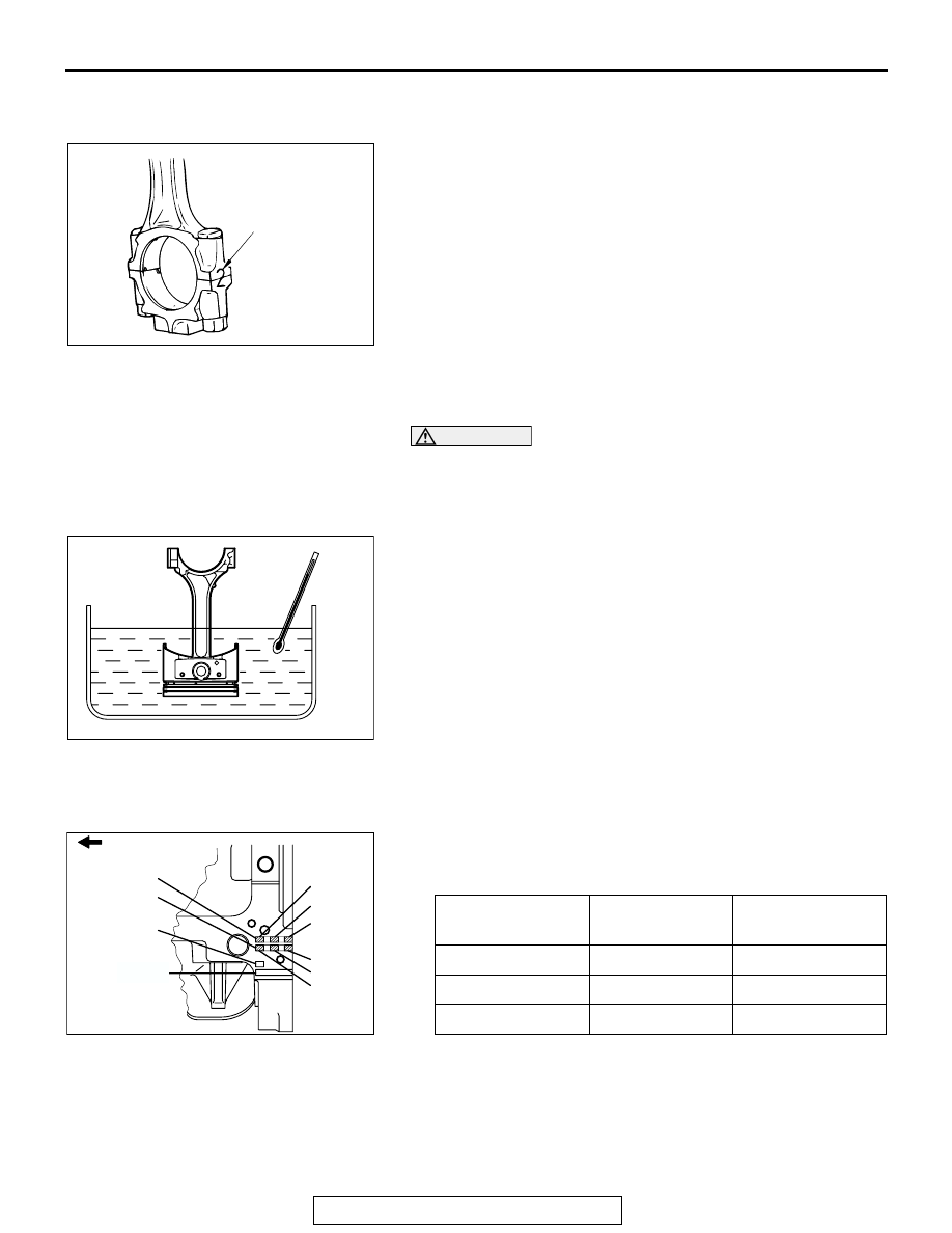
<<A>> CONNECTING ROD CAP REMOVAL
1. Mark the cylinder number on the side of the connecting rod 

big end for correct reassembly.

2. Keep the removed connecting rods, caps, and bearings in 

order according to the cylinder number.

.

<<B>> PISTON PIN REMOVAL
1. Remove the snap rings.

CAUTION

The clearance between the piston and the piston pin is an 
almost tight fit at room temperature. Therefore, be sure the 
heat the piston before pulling out the piston pin. In addi-
tion, note that the piston is hot after heating.
2. Heat the piston approximately 70

°C (158°F) and pull out the 

piston pin.

INSTALLATION SERVICE POINTS

.

>>A<< PISTON PIN INSTALLATION
1. When replacing the piston pin, read off the cylinder bore size 

mark on the cylinder block as illustrated, and select a piston 
according to the flowing table.

NOTE: The piston size mark shows on the top of the piston.

2. Set the snap ring into one side of the piston pin hole.

AKX00734

CYLINDER
NUMBER

AB

AKX01397

70˚C

(158˚F)

AB

CYLINDER BORE 
SIZE MARK

PISTON CLASS PISTON SIZE 

MARK

I

A

A

II

B

None

III

C

C

AK200850

TIMING BELT SIDE

CHECK DEGIT

No.4

No.1

No.2

No.3

AC

LEFT BANK

RIGHT BANK

No.6

No.5

CRANKSHAFT 
BORE SIZE
MARK

PISTON AND CONNECTING ROD

TSB Revision

ENGINE OVERHAUL

11B-42

CAUTION

Apply ample coat of engine oil to the periphery of the pis-
ton pin and the hole of the connecting rod small end. The 
clearance between the piston and the piston pin is an 
almost tight fit at room temperature. Therefore, be sure to 
heat the piston before inserting the piston pin. In addition, 
note that the piston is hot after heating. 
3. Heat the piston to approximately 70

°C (158°F).

4. With the front mark of the connecting rod and that of the 

piston located on the same side, insert the piston pin.

5. Set the snap ring into the other side of the piston pin hole.

6. Check that the piston moves smoothly.

.

AKX01398

70˚C

(158˚F)

AB

AK201080

FRONT MARK 74

AB

FRONT MARK

AKX00716

PISTON AND CONNECTING ROD

TSB Revision

ENGINE OVERHAUL

11B-43

>>B<<OIL RING INSTALLATION
1. Fit the oil ring spacer into the piston ring groove.

NOTE: The side rails and spacer may be installed in either 
direction.

CAUTION

Do not use any piston ring expander when installing the 
side rail.
2. Install the upper side rail.

To install the side rail, first fit one end of the rail into the 
piston groove, then press the remaining portion into the 
position by finger. See illustration.
Use of a ring expander to expand the side rail end gap can 
break the side rail, unlike other piston rings.

3. Install the lower side rail in the same procedure as described 

in step (2).

4. Make sure that the side rails move smoothly in either 

direction.

.

>>C<< PISTON RING NO.2/PISTON RING NO.1 
INSTALLATION 
1. To prevent wrong installation, check the identification mark 

of each piston ring. The identification mark is stamped near 
the ring gap:

Identification mark

Number 1 ring: 1T
Number 2 ring: 2T

NOTE: Size marks on piston rings are as follows.

2. Using a piston ring expander, fit the number 2 piston ring 

into the number 2 groove of piston.
NOTE: Install the piston rings with their identification mark 
facing up, to the piston crown side.

3. Install the number 1 piston ring in the same manner as step 

2.

.

AK000196AB

SIDE RAIL

SIDE RAIL

SPACER

AKX00608

SIDE RAIL END

AB

SIZE

SIZE MARK

Standard

None

0.25 mm (0.010 in) oversize 
diameter

25

0.50 mm (0.020 in) oversize 
diameter

50

AKX00689

NO.1

NO.2

IDENTIFICATION 
MARK

SIZE MARK

IDENTIFICATION MARK

AB

AKX00633

PISTON AND CONNECTING ROD

TSB Revision

ENGINE OVERHAUL

11B-44

>>D<< CONNECTING ROD BEARING INSTALLATION
1. Measure the crankshaft pin diameter and confirm its 

classification from the following table. In the case of a 
crankshaft supplied as a service part, identification colors/
marks of its pins are painted/stamped at the positions shown 
in the illustration.

2. From the following table, select a bearing whose size is 

appropriate for the crankshaft pin outside the diameter. 
If the crankshaft pin outside diameter Identification color is 
"yellow" and the connecting rod Identification mark is "2," for 
example, select a bearing whose Identification color is 
"green."
If there is no Identification color paint on the crankshaft, 
measure the pin outside diameter and select bearing 
appropriate for the measured value.

3. Install the selected bearing in the big end and in the cap of 

the connecting rod.

.

AKX00634

NO.5

LOCATION OF IDENTIFICATION COLOR

NO.2

NO.4

NO.1

NO.3

NO.6

AB

CRANKSHAFT PIN OUTSIDE DIAMETER

CONNECTING ROD

BEARING

IDENTIFICATION COLOR SIZE mm (in)

IDENTIFICATION MARK IDENTIFICATION

COLOR

Yellow

54.994 

− 55.000

(2.1651 

− 2.1654)

0

Pink

1

Red

2

Green

None

54.988 

− 54.994

(2.1649 

− 2.1651)

0

Red

1

Green

2

Black

White

54.982 

− 54.988

(2.1646 

− 2.1649)

0

Green

1

Black

2

Brown

AK000449

IDENTIFICATION MARK

AB

AKX00635

IDENTIFICATION
COLOR

AB


Content   ..  450  451  452  453   ..