Mitsubishi Montero (2002-2004). Manual - part 453


  Index      Mitsubishi     Mitsubishi Montero - service repair manual 2002-2004 year


Search            


Content   ..  451  452  453  454   ..


Mitsubishi Montero (2002-2004). Manual - part 453


PISTON AND CONNECTING ROD

TSB Revision

ENGINE OVERHAUL

11B-45

>>E<< PISTON AND CONNECTING ROD INSTALLATION
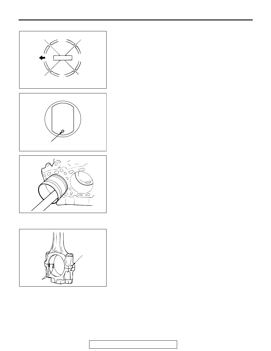
1. Liberally coat the circumference of the piston, piston ring, 

and oil ring with engine oil.

2. Arrange the piston ring and oil ring gaps (side rail and 

spacer) as shown in the illustration.

3. Rotate the crankshaft so that the crank pin is on the center 

of the cylinder bore.

4. Insert the piston and connecting rod assembly into the 

cylinder with the front mark on the piston crown pointing to 
the timing belt side.

5. Using a suitable piston ring compressor tool, install the 

piston and connecting rod assembly into the cylinder block.

.

>>F<< CONNECTING ROD CAP INSTALLATION
1. Verifying the mark made during disassembly, install the 

bearing cap to the connecting rod. If the connecting rod is 
new with no index mark, make sure that the bearing locking 
notches are on the same side as shown.

AKX00620

UPPER
SIDE RAIL

NO.1

PISTON PIN

TIMING
BELT SIDE

LOWER
SIDE RAIL

NO.2 RING GAP 
AND SPACER GAP

AB

AK201081AB

FRONT MARK

AKX00721

AKX00735

CYLINDER NO.

NOTCHES

AB

PISTON AND CONNECTING ROD

TSB Revision

ENGINE OVERHAUL

11B-46

2. Make sure that the connecting rod big end side clearance 

meets the specification.

Standard value: 0.10 

 0.25 mm (0.004  0.009 inch)

Limit: 0.4 mm (0.02 inch)

.

>>G<< CONNECTING ROD CAP NUT INSTALLATION
1. The connecting rod bolts should be examined before reuse. 

If the bolt threads are damaged, the bolt should be replaced.
Hand-thread the nut to the full length of the bolt threads. If 
the nut does not run down smoothly, the bolt should be 
replaced.

2. Before installation of each nut, apply engine oil to the 

threaded portion and bearing surface of the nut.

3. Loosely tighten each nut to the bolt.
4. Then tighten the nuts alternately to a torque of 27 

± 2 N⋅m 

(20 

± 1 ft-lb) to install the cap properly.

5. Make a paint mark on the head of each nut.
6. Make a paint mark on the bolt end at the position 90 degree 

angle (1/4 turn) to 94 degree angle from the paint mark 
made on the nut in the direction of tightening the nut.

CAUTION

• If the nut is turned less than 90 degree angle (1/4 turn), 

proper fastening performance may not be achieved. Be 
careful to tighten the nut exactly 90 degree angle (1/4 
turn).

• If the nut is overtightened (exceeding 94 degree angle), 

loosen the nut completely and then retighten it by 
repeating the tightening procedure from step 3.

7. Turn the nut further 90 degree angle (1/4 turn) to 94 degree 

angle and make sure that the paint marks on the nut and 
bolt are aligned.

INSPECTION

M1113008500280

.

PISTON
Replace the piston if scratches or seizure is evident on its sur-
faces (especially the thrust surface). Replace the piston if it is 
cracked.

.

PISTON PIN
1. Insert the piston pin into the piston pin hole with a thumb. 

You should feel a slight resistance. Replace the piston pin if 
it can be easily inserted or there is an excessive play.

2. The piston and piston pin must be replaced as an assembly.

AK201530

AKX01401AB

1/4TURN

PAINT

MARKS

NUT

BOLT

PAINT

MARKS

PISTON AND CONNECTING ROD

TSB Revision

ENGINE OVERHAUL

11B-47

.

PISTON RING 
1. Check the piston ring for damage, excessive wear, and 

breakage and replace if defects are evident. If the piston has 
been replaced with a new one, the piston rings must also be 
replaced with new ones.

2. Check for clearance between the piston ring and ring 

groove. If the limit is exceeded, replace the ring or piston, or 
both.

Standard value:
Number 1: 0.03 

 0.07 mm (0.0012  0.0027 inch)

Number 2: 0.02 

 0.06 mm (0.0008  0.0023 inch)

Limit: 0.1 mm (0.003 inch)

3. Insert the piston ring into the cylinder bore. Force the ring 

down with a piston, the piston crown being in contact with 
the ring, to correctly position it at right angles to the cylinder 
wall. Then, measure the end gap with a feeler gauge.
If the ring gap is excessive, replace the piston ring.

Standard value:
Number 1: 0.25 

 0.40 mm (0.010  0.016 inch)

Number 2: 0.35 

 0.50 mm (0.014  0.020 inch)

Oil: 0.10 

 0.35 mm (0.004  0.014 inch)

Limit:
Number 1, Number 2: 0.8 mm (0.03 inch)
Oil: 1.0 mm (0.03 inch)

.

CRANKSHAFT PIN OIL CLEARANCE 
<PLASTIC GAUGING MATERIAL METHOD>
The crankshaft oil clearance can be measured easily by using 
plastic gauging material, as follows:
1. Remove oil from the crankshaft pin and the bearing inner 

surface.

2. Cut plastic gauging material to the same length as the width 

of the bearing and place it on the pin in parallel with its axis.

3. Install the connecting rod cap carefully and tighten the nuts 

to the specified torque.

4. Carefully remove the connecting rod cap.
5. Measure the width of the smashed plastic gauging material 

at its widest section by using a scale printed on the plastic 
gauging material bag.

Standard value: 0.02 

 0.04 mm (0.0008  0.0016 inch)

Limit: 0.1 mm (0.003 inch)

AKX00612

AKX00719

PUSH IN BY
PISTON

PISTON
RING GAP

PISTON RING

AB

AKX00731AB

SCALE

CRANKSHAFT AND CYLINDER BLOCK

TSB Revision

ENGINE OVERHAUL

11B-48

CRANKSHAFT AND CYLINDER BLOCK

REMOVAL AND INSTALLATION

M1113008700422

Required Special Tool:

• MD998718: Crankshaft Rear Oil Seal Installer

AK201082 AB

1

2

3

4

5

6

14

15

16

13

12

11

10

9

8

23 ± 2 N·m
17 ± 1 ft-lb

74 ± 4 N·m
54 ± 3 ft-lb

74 ± 2 N·m
54 ± 1 ft-lb

28 ± 2 N·m
21 ± 1 ft-lb

11 ± 1 N·m
97 ± 9 in-lb

11 ± 1 N·m
97 ± 9 in-lb

APPLY ENGINE OIL
TO ALL MOVING
PARTS BEFORE
INSTALLTION.

7

9 ± 2 N·m
79 ± 18 in-lb

REMOVAL STEPS

1. ADAPTER PLATE
2. DRIVE PLATE
3. CRANKSHAFT ADAPTOR
4. REAR PLATE

>>F<<

5. OIL SEAL CASE 

>>E<<

6. CRANKSHAFT REAR OIL SEAL
7. BAFFLE PLATE

>>D<<

8. BEARING CAP BOLT

>>D<<

9. BEARING CAP

>>B<<

10. CRANKSHAFT BEARING, LOWER
11. CRANKSHAFT

>>C<<

12. THRUST BEARING

>>B<<

13. CRANKSHAFT BEARING, UPPER
14. KNOCK SENSOR

>>A<<

15. KNOCK SENSOR BRACKET
16. CYLINDER BLOCK

REMOVAL STEPS (Continued)


Content   ..  451  452  453  454   ..