Mitsubishi Montero (2002-2004). Manual - part 450
CYLINDER HEAD AND VALVES
TSB Revision
ENGINE OVERHAUL
11B-33
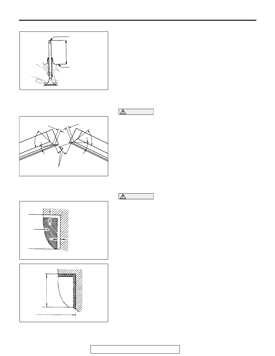
VALVE SEAT
Assemble the valve, then measure the valve stem projection
between the end of the valve stem and the spring seating sur-
face. If the measurement exceeds the specified limit, replace
the valve seat.
Standard value:
<Intake> 48.30 mm (1.9021 inches)
<Exhaust>51.71 mm (2.039 inches)
Limit:
<Intake> 48.80 mm (1.921 inches)
<Exhaust> 52.01 mm (2.048 inches)
.
VALVE SEAT RECONDITIONING PROCEDURE
CAUTION
Before correcting the valve seat, check for the clearance
between the valve guide and valve and, if necessary,
replace the valve guide.
1. Using the special tool or a seat grinder, correct to obtain the
specified seat width and angle.
2. After correcting the valve seat, lap the valve and valve seat
using lapping compound. Then, check the valve stem
projection.
.
VALVE SEAT REPLACEMENT PROCEDURE
CAUTION
Before replacing the valve seat, check the valve guide and,
if necessary, replace the valve guide.
1. Cut the valve seat from the inside to thin the wall thickness.
Then, remove the valve seat.
2. Rebore the valve seat hole in the cylinder head to a selected
oversize valve seat diameter.
Seat ring hole diameter:
Intake valve
0.3 oversize 37.80
− 37.83 mm (1.4882 − 1.4894 inches)
0.6 oversize 38.10
− 38.13 mm (1.5000 − 1.5012 inches)
Exhaust valve
0.3 oversize 34.80
− 34.83 mm (1.3701 − 1.3713 inches)
0.6 oversize 35.10
− 35.13 mm (1.3819 − 1.3831 inches)
3. Before fitting the valve seat, either heat the cylinder head up
to approximately 250
°C (482°F) or cool the valve seat in
liquid nitrogen, to prevent the cylinder head bore from
galling.
AKX00695
SPRING SEATING
SURFACE
VALVE STEM END
VALVE STEM
PROJECTION
AB
AK101830AB
0.9
– 1.3 mm
0.9 – 1.3 mm
65˚
65˚
15˚
25˚
43.5˚
– 44˚
AKX00610
0.5 – 1 mm
(0.020 – 0.039 in)
0.5 – 1 mm (0.020 – 0.039 in)
CUT
AWAY
AB
AKX00611
HEIGHT OF
SEAT RING
OVERSIZE DIAMETER
AB