Mitsubishi Montero (2002-2004). Manual - part 448
ROCKER ARMS AND CAMSHAFT
TSB Revision
ENGINE OVERHAUL
11B-25
ROCKER ARM
1. Check the roller surface and replace the rocker arm if
recesses, damage or heat seizure is observed.
2. Check roller rotation and replace the rocker arm if uneven
rotation or roller backlash of the roller is observed.
3. Check the inside diameter and replace the rocker arm if
damage or seizure is observed.
.
CAMSHAFT
1. Check the camshaft bearing journals for damage and
binding. If the journals are binding, check the cylinder head
for damage. Also check the cylinder head for clogged oil
holes.
2. Check the tooth surface of the distributor drive gear teeth of
the camshaft and replace if abnormal wear is evident.
3. Check the cam surface for abnormal wear and damage and
replace if necessary. Also measure the cam height and
replace if out of minimum limit.
Standard value:
Intake 37.39 mm (1.472 inches)
Exhaust 37.14 mm (1.462 inches)
Minimum limit:
Intake 36.89 mm (1.452 inches)
Exhaust 36.64 mm (1.443 inches)
.
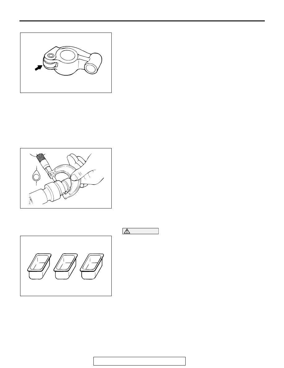
LASH ADJUSTERS
CAUTION
• The lash adjusters are precision-engineered mecha-
nisms. Do not allow them to become contaminated by
dirt or other foreign substances.
• Do not attempt to disassemble the lash adjusters.
• Use only fresh diesel fuel to clean the lash adjusters.
1. Prepare three containers and approximately 5 dm
3
(30.5
quart) of diesel fuel. Into each container, pour enough diesel
fuel to completely cover a lash adjuster when it is standing
upright. Then, perform the following steps with each lash
adjuster.
AKX00723
ROLLER TIP
AB
AKX00685
AKX00625
OUTSIDE
CLEANING
INSIDE
CLEANING
FILLING
DIESEL FUEL
A
B
C
AB