Mitsubishi Montero (2002-2004). Manual - part 320


  Index      Mitsubishi     Mitsubishi Montero - service repair manual 2002-2004 year


Search            


Content   ..  318  319  320  321   ..


Mitsubishi Montero (2002-2004). Manual - part 320


SYMPTOM PROCEDURES

TSB Revision

SWS SYMPTOM PROCEDURES

54Bb-327

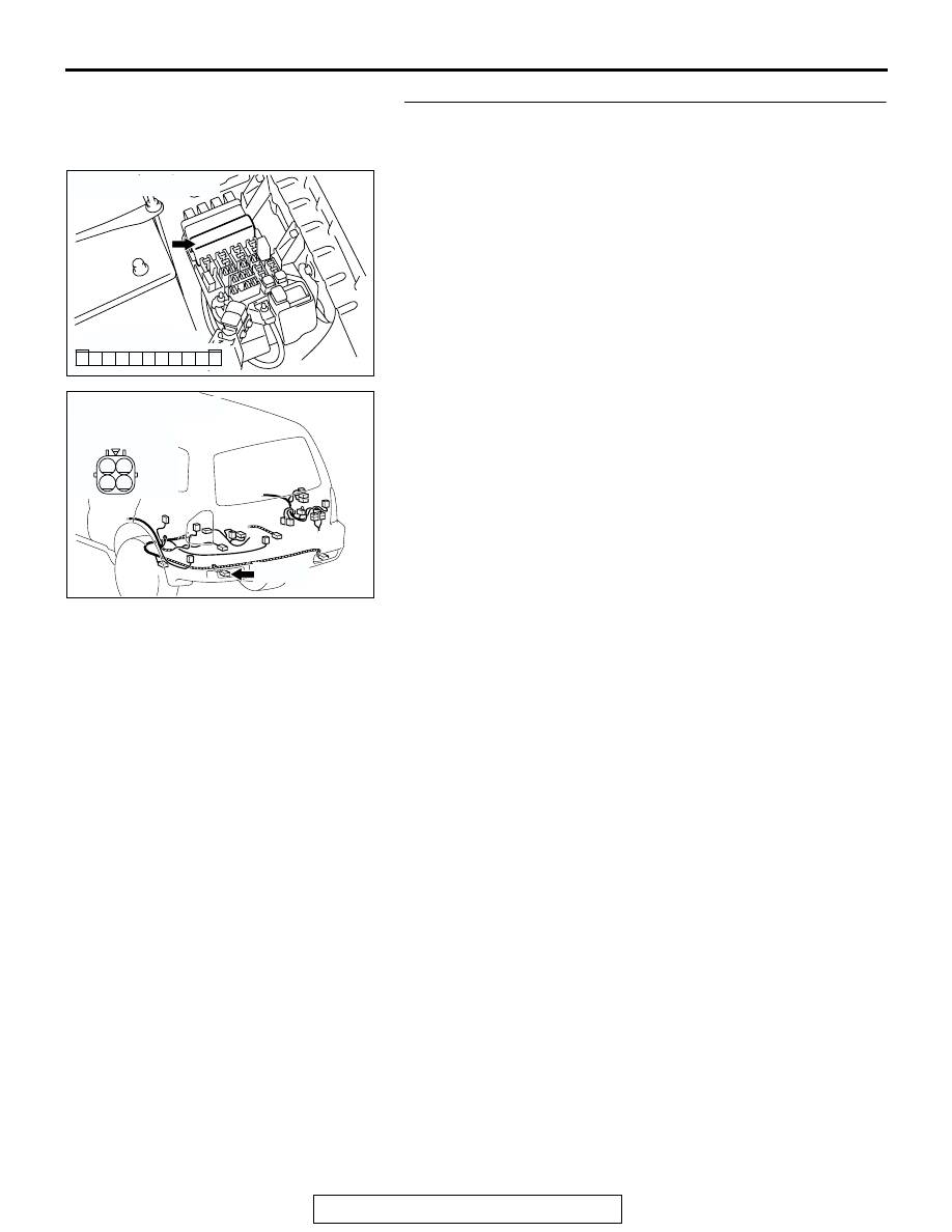
STEP 7. Check the wiring harness between taillight (LH) 
connector G-16 (terminal 1) and front-ECU connector A-
07X (terminal 8).

AC204183

CONNECTOR : A-07X

AB

2 1

3

4

6

7

8

9

5

11 10

RELAY BOX SIDE

AC204179

CONNECTOR : G-16

AH

HARNESS SIDE

G-16(B)

G-16(B)

3

4

2

1

SYMPTOM PROCEDURES

TSB Revision

SWS SYMPTOM PROCEDURES

54Bb-328

NOTE: Also check intermediate connectors D-28, D-111 and F-
10 for loose, corroded, or damaged terminals, or terminals 
pushed back in the connector. If intermediate connector D-28, 
D-111 or F-10 is damaged, repair or replace the damaged com-
ponent(s) as described in GROUP 00E, Harness Connector 
Inspection 

P.00E-2

.

Q: Is the wiring harness between taillight (LH) connector 

G-16 (terminal 1) and front-ECU connector A-07X 
(terminal 8) in good condition?
YES : 
No action is necessary and testing is complete.
NO :  The wiring harness may be damaged or the 

connector(s) may have loose, corroded or damaged 
terminals, or terminals pushed back in the connector. 
Repair the wiring harness as necessary. Verify that 
the taillight (RH) and side marker light (RH) 
illuminates normally.

AC204170

CONNECTOR : D-28

AI

2 3

27

32

28

33

16

15

4 5

19

18

29

17

34

7 8

35

22

21

9 10

30

36

31

37

25

24

23

6

20

1

14

26

11

13

12

38

AC204171

CONNECTOR : D-111

AC

9

8

6 7

5

3 4

20

32

21

33

43

17 18

30

41

16

29

28

39 40

13

25

12

24

35 36

14

26

37

15

27

38

19

31

42

1

10

22

2

11

23

34

AC204178

CONNECTOR : F-10

AD

F-10(GR)

F-10(GR)

3

1

2

4

5

6

SYMPTOM PROCEDURES

TSB Revision

SWS SYMPTOM PROCEDURES

54Bb-329

STEP 8. Check the ground circuit to the position light (LH). 
Test at position light (LH) connector A-18. 
(1) Disconnect position light (LH) connector A-18 and measure 

the resistance available at the wiring harness side of the 
connector.

(2) Measure the resistance value between terminal 1 and 

ground.

• The resistance should equal 2 ohms or less.

Q: Is the measured resistance 2 ohms or less?

YES : No action is necessary and testing is complete.
NO :  Go to Step 9.

STEP 9. Check position light (LH) connector A-18 for 
loose, corroded or damaged terminals, or terminals 
pushed back in the connector.
Q: Is position light (LH) connector A-18 in good condition?

YES : Go to Step 10.
NO :  Repair or replace the damaged component(s). Refer 

to GROUP 00E, Harness Connector Inspection 

P.00E-2

Verify that the position light illuminates 

normally.

STEP 10. Check the wiring harness between position light 
(LH) connector A-18 (terminal 1) and ground.
Q:  Is the wiring harness between position light (LH) 

connector A-18 (terminal 1) and ground in good 
condition?
YES : 
No action is necessary and testing is complete.
NO :  The wiring harness may be damaged or the 

connector(s) may have loose, corroded or damaged 
terminals, or terminals pushed back in the connector. 
Repair the wiring harness as necessary. Verify that 
the position light illuminates normally.

AC204167

CONNECTOR : A-18

HARNESS 
SIDE

A-18(GR)

A-18(GR)

AG

2 1

AC100264

2 1

AB

CONNECTOR A-18
(HARNESS SIDE)

AC204167

CONNECTOR : A-18

HARNESS 
SIDE

A-18(GR)

A-18(GR)

AG

2 1

AC204167

CONNECTOR : A-18

HARNESS 
SIDE

A-18(GR)

A-18(GR)

AG

2 1

SYMPTOM PROCEDURES

TSB Revision

SWS SYMPTOM PROCEDURES

54Bb-330

STEP 11. Check the position light bulb (LH).
(1) Remove the position light bulb (LH).
(2) Verify that the position light bulb (LH) is not damaged or 

burned out.

Q: Is the position light bulb (LH) in good condition?

YES : Go to Step 12.
NO :  Replace the position light bulb (LH). Verify that the 

position light (LH) illuminates normally.

STEP 12. Check the ground circuit to the position light 
(LH). Test at position light (LH) connector A-18. 
(1) Disconnect position light (LH) connector A-18 and measure 

the resistance available at the wiring harness side of the 
connector.

(2) Measure the resistance value between terminal 1 and 

ground.

• The resistance should equal 2 ohms or less.

Q: Is the measured resistance 2 ohms or less?

YES : Go to Step 15.
NO :  Go to Step 13.

STEP 13. Check position light (LH) connector A-18 for 
loose, corroded or damaged terminals, or terminals 
pushed back in the connector.
Q: Is position light (LH) connector A-18 in good condition?

YES : Go to Step 14.
NO :  Repair or replace the damaged component(s). Refer 

to GROUP 00E, Harness Connector Inspection 

P.00E-2

. Verify that the position light (LH) illuminates 

normally.

AC204167

CONNECTOR : A-18

HARNESS 
SIDE

A-18(GR)

A-18(GR)

AG

2 1

AC100264

2 1

AB

CONNECTOR A-18
(HARNESS SIDE)

AC204167

CONNECTOR : A-18

HARNESS 
SIDE

A-18(GR)

A-18(GR)

AG

2 1


Content   ..  318  319  320  321   ..