Mitsubishi Montero (2002-2004). Manual - part 318


  Index      Mitsubishi     Mitsubishi Montero - service repair manual 2002-2004 year


Search            


Content   ..  316  317  318  319   ..


Mitsubishi Montero (2002-2004). Manual - part 318


SYMPTOM PROCEDURES

TSB Revision

SWS SYMPTOM PROCEDURES

54Bb-319

DIAGNOSIS

Required Special Tools:

• MB991223: Harness Set

• MB991502: Scan Tool (MUT-II) 

• MB991862: SWS monitor kit 

Use scan tool MB991502 to select "ECU COMM CHK" on 
the SWS monitor display.
Check the following ECUs:

• ETACS-ECU

• Column-ECU

• Front-ECU

CAUTION

To prevent damage to scan tool MB991502, always turn the 
ignition switch to the "LOCK" (OFF) position before con-
necting or disconnecting scan tool MB991502.
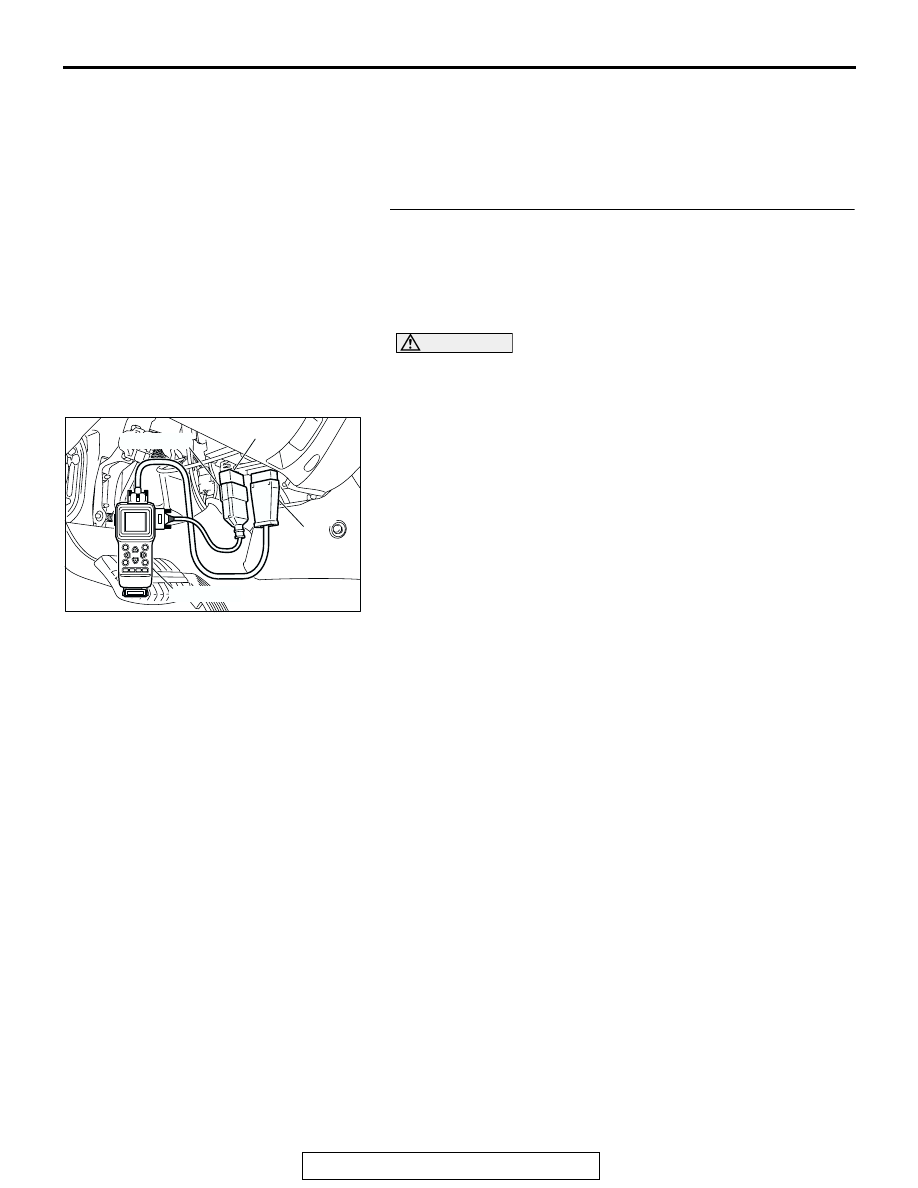
(1) Connect scan tool MB991502 to the data link connector 

(16-pin).

(2) Connect SWS monitor kit MB991862 to the data link 

connector (13-pin).

(3) Turn the ignition switch to the "LOCK" (OFF) position.
(4) Operate scan tool MB991502 according to the procedure 

below to display "ECU COMM CHK."

1. Select "SYSTEM SELECT."
2. Select "SWS."
3. Select "SWS MONITOR."
4. Select "ECU COMM CHK."

(5) Scan tool MB991502 should show "OK" on the "ECU 

COMM CHK" menus for the "ETACS ECU", "COLUMN 
ECU" and "FRONT ECU" menus.

Q: Is "OK" displayed on the "ETACS ECU", "COLUMN 

ECU" and "FRONT ECU" menus?
"OK" are displayed for all the items : 
Replace the front-

ECU. Verify that the headlights and the taillights 
illuminate normally.

"NG" is displayed on the "ETACS ECU" menu : Refer to 

Inspection Procedure A-3 "Communication with 
ETACS-ECU is not possible 

P.54Bb-25

."

"NG" is displayed on the "COLUMN ECU" menu : Refer 

to Inspection Procedure A-2 "Communication with 
column switch (column-ECU) is not possibl

P.54Bb-

25

."

"NG" is displayed on the "FRONT ECU" menu : Refer to 

Inspection procedure A-4 "Communication with front-
ECU is not possible 

P.54Bb-32

."

AC204222AB

16-pin

13-pin

MB991502

MB991862

SYMPTOM PROCEDURES

TSB Revision

SWS SYMPTOM PROCEDURES

54Bb-320

INSPECTION PROCEDURE J-6: Headlight and Taillight: Any of taillights, the position lights, the side 
marker light or the license plate lights do not illuminate.

Taillights, Position Lights and License Plate Lights Circuit

SYMPTOM PROCEDURES

TSB Revision

SWS SYMPTOM PROCEDURES

54Bb-321

.

TECHNICAL DESCRIPTION (COMMENT)
If the position lights, the taillights, the side marker 
lights or the license plate lights do not illuminate, 
their bulb may be defective.

.

TROUBLESHOOTING HINTS

• The position light bulb may be defective

• The stop/taillight bulb may be defective

• The side marker light bulb may be defective

• The license plate light bulb may be defective

• The wiring harness or connectors may have 

loose, corroded, or damaged terminals, or termi-
nals pushed back in the connector

AC204183

CONNECTOR : A-07X

AG

AC204167

CONNECTOR : A-18

A-18(GR)

AN

AC204166

CONNECTOR : A-36

AO

A-36(GR)

AC204170

CONNECTORS : D-28, D-125

BR

D-28

D-125

AC204171

CONNECTOR : D-111

AG

AC204178

CONNECTOR : F-10

F-10(GR)

AJ

AC204179

CONNECTORS : G-02, G-09, G-10, G-12, G-16

G-02(B)

G-16(B)

G-12(B)

G-10

G-09(B)

AI

AC204182

CONNECTOR : I-04

AF

SYMPTOM PROCEDURES

TSB Revision

SWS SYMPTOM PROCEDURES

54Bb-322

DIAGNOSIS

Required Special Tool:

• MB991223: Harness Set

STEP 1. Verify the operation of each light.
Q: Which light does not illuminate?

taillight (LH), license plate light and side marker light 
(LH) : 
Go to Step 2.
taillight (RH) and side marker light (RH) : Go to Step 4.
taillight (LH) and license plate : Go to Step 6.
position light : Go to Step 8.
position light (LH) : Go to Step 11.
position light (RH) : Go to Step 17.
taillight : Go to Step 23.
taillight (LH) : Go to Step 26.
taillight (RH) : Go to Step 32.
license plate lights : Go to Step 38.
side marker light (LH) : Go to Step 44.
side marker light (RH) : Go to Step 50.
All lights : Refer to Inspection Procedure J-1 "Tail lights do 

not illuminate 

P.54Bb-304

."

STEP 2. Check rear combination light (LH) connector G-02 
and front-ECU connector A-07X for loose, corroded or 
damaged terminals, or terminals pushed back in the 
connector.
Q: Are rear combination light (LH) connector G-02 and 

front-ECU connector A-07X in good condition?
YES : 
Go to Step 3.
NO :  Repair or replace the damaged component(s). Refer 

to GROUP 00E, Harness Connector Inspection 

P.00E-2

Verify that the taillight (LH), license plate 

light and side marker light (LH) illuminates normally.

AC204183

CONNECTOR : A-07X

AB

2 1

3

4

6

7

8

9

5

11 10

RELAY BOX SIDE

AC204179

CONNECTOR : G-02

AB

HARNESS SIDE

G-02(B)

G-02(B)

1

4

2

3

5

6


Content   ..  316  317  318  319   ..