Mitsubishi Montero (2002-2004). Manual - part 319


  Index      Mitsubishi     Mitsubishi Montero - service repair manual 2002-2004 year


Search            


Content   ..  317  318  319  320   ..


Mitsubishi Montero (2002-2004). Manual - part 319


SYMPTOM PROCEDURES

TSB Revision

SWS SYMPTOM PROCEDURES

54Bb-323

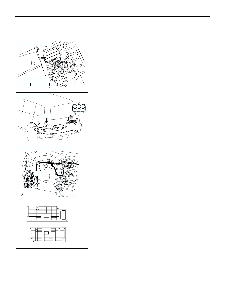
STEP 3. Check the wiring harness between rear 
combination light (LH) connector G-02 (terminal 1) and 
front-ECU connector A-07X (terminal 8).

NOTE: Also check intermediate connectors D-28 and D-125 for 
loose, corroded, or damaged terminals, or terminals pushed 
back in the connector. If intermediate connector D-28 or D-125 
is damaged, repair or replace the damaged component(s) as 
described in GROUP 00E, Harness Connector Inspection 

P.00E-2

.

Q: Is the wiring harness between rear combination light 

(LH) connector G-02 (terminal 1) and front-ECU 
connector A-07X (terminal 8) in good condition?
YES : 
No action is necessary and testing is complete.
NO :  The wiring harness may be damaged or the 

connector(s) may have loose, corroded or damaged 
terminals, or terminals pushed back in the connector. 
Repair the wiring harness as necessary. Verify that 
the taillight (LH), license plate light and side marker 
light (LH) illuminates normally.

AC204183

CONNECTOR : A-07X

AB

2 1

3

4

6

7

8

9

5

11 10

RELAY BOX SIDE

AC204179

CONNECTOR : G-02

AB

HARNESS SIDE

G-02(B)

G-02(B)

1

4

2

3

5

6

AC204188

CONNECTORS : D-28, D-125

AP

D-28

D-28

D-125

D-125

2 3

27

32

28

33

16

15

4 5

19

18

29

17

34

7 8

35

22

21

9 10

30

36

31

37

25

24

23

6

20

1

14

26

11

13

12

38

9

8

6 7

5

3 4

20

32

21

33

43

17 18

30

41

16

29

28

39 40

13

25

12

24

35 36

14

26

37

15

27

38

19

31

42

1

10

22

2

11

23

34

SYMPTOM PROCEDURES

TSB Revision

SWS SYMPTOM PROCEDURES

54Bb-324

STEP 4. Check rear combination light (RH) connector G-09 
and front-ECU connector A-07X for loose, corroded or 
damaged terminals, or terminals pushed back in the 
connector.
Q: Are rear combination light (RH) connector G-09 and 

front-ECU connector A-07X in good condition?
YES : 
Go to Step 5.
NO :  Repair or replace the damaged component(s). Refer 

to GROUP 00E, Harness Connector Inspection 

P.00E-2

. Verify that the taillight (RH) and side marker 

light (RH) illuminates normally.

AC204183

CONNECTOR : A-07X

AB

2 1

3

4

6

7

8

9

5

11 10

RELAY BOX SIDE

AC204179

CONNECTOR : G-09

AC

HARNESS SIDE

G-09(B)

G-09(B)

1

4

2

3

5

6

SYMPTOM PROCEDURES

TSB Revision

SWS SYMPTOM PROCEDURES

54Bb-325

STEP 5. Check the wiring harness between rear 
combination light (RH) connector G-09 (terminal 1) and 
front-ECU connector A-07X (terminal 8).

NOTE: Also check intermediate connectors D-28 and D-111 for 
loose, corroded, or damaged terminals, or terminals pushed 
back in the connector. If intermediate connector D-28 or D-111 
is damaged, repair or replace the damaged component(s) as 
described in GROUP 00E, Harness Connector Inspection 

P.00E-2

.

Q: Is the wiring harness between rear combination light 

(RH) connector G-09 (terminal 1) and front-ECU 
connector A-07X (terminal 8) in good condition?
YES : 
No action is necessary and testing is complete.
NO :  The wiring harness may be damaged or the 

connector(s) may have loose, corroded or damaged 
terminals, or terminals pushed back in the connector. 
Repair the wiring harness as necessary. Verify that 
the taillight (RH) and side marker light (RH) 
illuminates normally.

AC204183

CONNECTOR : A-07X

AB

2 1

3

4

6

7

8

9

5

11 10

RELAY BOX SIDE

AC204179

CONNECTOR : G-09

AC

HARNESS SIDE

G-09(B)

G-09(B)

1

4

2

3

5

6

AC204170

CONNECTOR : D-28

AI

2 3

27

32

28

33

16

15

4 5

19

18

29

17

34

7 8

35

22

21

9 10

30

36

31

37

25

24

23

6

20

1

14

26

11

13

12

38

AC204171

CONNECTOR : D-111

AC

9

8

6 7

5

3 4

20

32

21

33

43

17 18

30

41

16

29

28

39 40

13

25

12

24

35 36

14

26

37

15

27

38

19

31

42

1

10

22

2

11

23

34

SYMPTOM PROCEDURES

TSB Revision

SWS SYMPTOM PROCEDURES

54Bb-326

STEP 6. Check taillight (LH) connector G-16 and front-ECU 
connector A-07X for loose, corroded or damaged 
terminals, or terminals pushed back in the connector.
Q: Are taillight (LH) connector G-16 and front-ECU 

connector A-07X in good condition?
YES : 
Go to Step 7.
NO :  Repair or replace the damaged component(s). Refer 

to GROUP 00E, Harness Connector Inspection 

P.00E-2

. Verify that the taillight (RH) and side marker 

light (RH) illuminates normally.

AC204183

CONNECTOR : A-07X

AB

2 1

3

4

6

7

8

9

5

11 10

RELAY BOX SIDE

AC204179

CONNECTOR : G-16

AH

HARNESS SIDE

G-16(B)

G-16(B)

3

4

2

1


Content   ..  317  318  319  320   ..