Mitsubishi Montero (2002-2004). Manual - part 252


  Index      Mitsubishi     Mitsubishi Montero - service repair manual 2002-2004 year


Search            


Content   ..  250  251  252  253   ..


Mitsubishi Montero (2002-2004). Manual - part 252


SYMPTOM PROCEDURES

TSB Revision

SWS SYMPTOM PROCEDURES

54Bb-55

INSPECTION PROCEDURE A-6: Communication with the RV meter is not possible.

NOTE: This troubleshooting procedure requires the 
use of scan tool MB991502 and SWS monitor kit 
MB991862. For details of how to use the SWS moni-
tor, refer to "How to use SWS monito

P.54Ba-8

."

.

TECHNICAL DESCRIPTION (COMMENT)
The RV meter or its power supply circuit or communi-
cation circuit may be defective.

.

TROUBLESHOOTING HINTS

• The RV meter may be defective

• The wiring harness or connectors may have 

loose, corroded, or damaged terminals, or termi-
nals pushed back in the connector

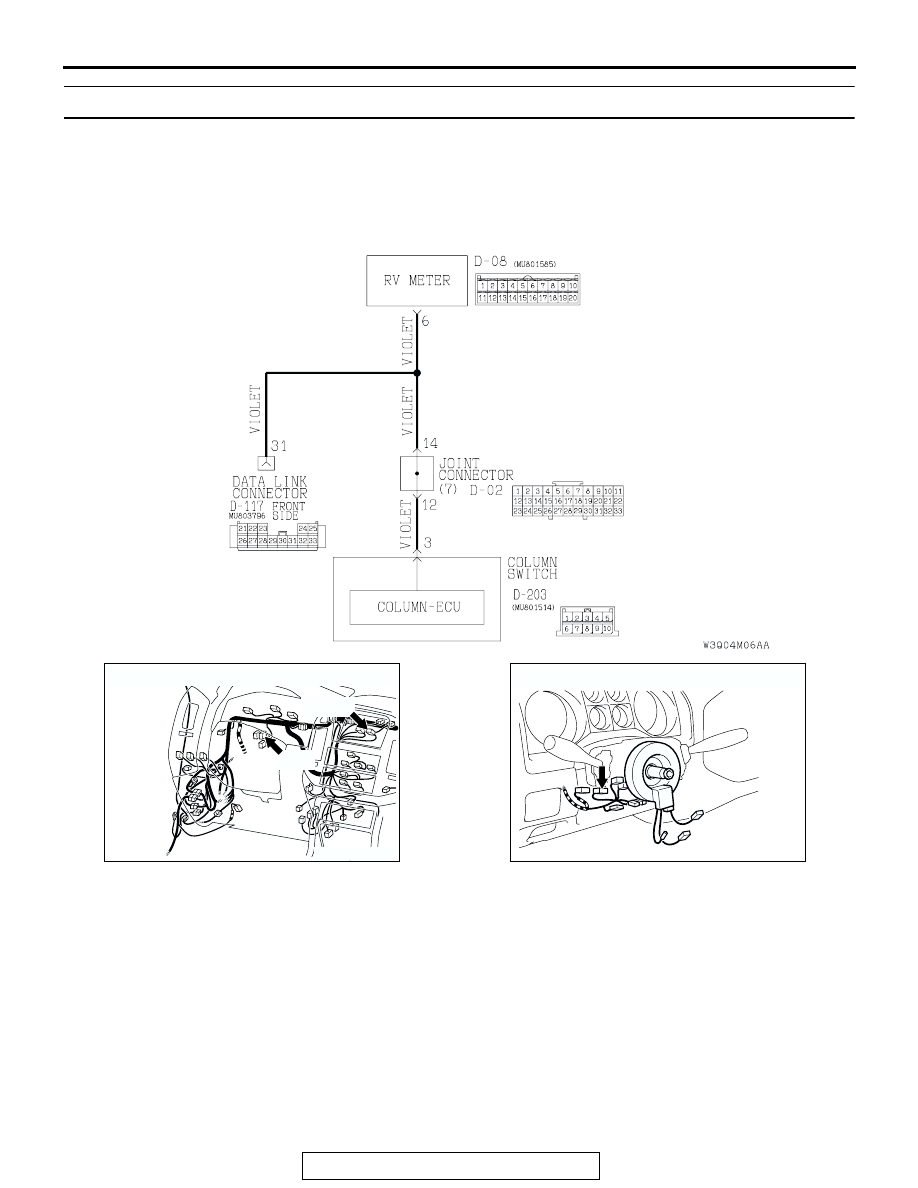
RV Meter and SWS Communication Circuit

AC204170

CONNECTORS : D-02, D-08

BG

D-08(B)

D-02

AC204172

CONNECTOR : D-203

AG

SYMPTOM PROCEDURES

TSB Revision

SWS SYMPTOM PROCEDURES

54Bb-56

DIAGNOSIS

Required Special Tools:

• MB991223: Harness Set 

• MB991502: Scan Tool (MUT-II)

• MB991862: SWS monitor kit

STEP 1. Use scan tool MB991502 to select "ECU COMM 
CHK" on the SWS monitor display.
Check the column-ECU.

CAUTION

To prevent damage to scan tool MB991502, always turn the 
ignition switch to the "LOCK" (OFF) position before con-
necting or disconnecting scan tool MB991502.
(1) Connect scan tool MB991502 to the data link connector 

(16-pin).

(2) Connect SWS monitor kit MB991862 to the data link 

connector (13-pin).

(3) Turn the ignition switch to the "LOCK" (OFF) position.
(4) Operate scan tool MB991502 according to the procedure 

below to display "ECU COMM CHK."

1. Select "SYSTEM SELECT."
2. Select "SWS."
3. Select "SWS MONITOR."
4. Select "ECU COMM CHK."

(5) Scan tool MB991502 should show "OK" on the "ECU 

COMM CHK" menu for the "COLUMN ECU" menu.

Q: Is "OK" displayed on the "COLUMN ECU" menu?

YES : Go to Step 2.
NO :  Refer to Inspection Procedure A-2 "Communication 

with column switch (column-ECU) is impossible 

P.54Bb-25

."

STEP 2. Check the RV meter.
Q: Does the RV meter work normally? 

YES : Go to Step 3.
NO :  Carry out troubleshooting for the RV meter first. Refer 

to GROUP 54A, RV mete

P.54A-189

.

AC204222AB

16-pin

13-pin

MB991502

MB991862

SYMPTOM PROCEDURES

TSB Revision

SWS SYMPTOM PROCEDURES

54Bb-57

STEP 3. Check RV meter connector D-08 and column 
switch connector D-203 for loose, corroded or damaged 
terminals, or terminals pushed back in the connector.
Q: Are RV meter connector D-08 and column switch 

connector D-203 in good condition? 
YES : 
Go to Step 4.
NO :  Repair or replace the damaged component(s). Refer 

to GROUP 00E, Harness Connector Inspection 

P.00E-2

. The system should communicate with the 

RV meter normally.

AC204170

CONNECTOR : D-08

AE

D-08(B)

HARNESS 
SIDE

D-08(B)

1

3

4

2

12

1413

11

6

7

8

10 9

18

19

20

16

17

5

15

AC204172

CONNECTOR : D-203

AC

HARNESS SIDE

1

2

3

7

8

6

5

10

4

9

D-203

SYMPTOM PROCEDURES

TSB Revision

SWS SYMPTOM PROCEDURES

54Bb-58

STEP 4. Check the wiring harness between RV meter 
connector D-08 (terminal 6) and column switch connector 
D-203 (terminal 3).
NOTE:  Also check joint connector D-02 for loose, corroded, or 
damaged terminals, or terminals pushed back in the connector. 
If joint connector D-02 is damaged, repair or replace the dam-
aged component(s) as described in GROUP 00E, Harness 
Connector Inspection 

P.00E-2

.

Q: Is the wiring harness between RV meter connector D-08 

(terminal 6) and column switch connector D-203 
(terminal 3) in good condition?
YES : 
Replace the RV meter. The system should 

communicate with the RV meter normally.

NO :  The wiring harness may be damaged or the 

connector(s) may have loose, corroded or damaged 
terminals, or terminals pushed back in the connector. 
Repair the wiring harness as necessary. The system 
should communicate with the RV meter normally.

TONE ALARM

GENERAL DESCRIPTION CONCERNING TONE ALARM

M1549021000081

The ECU related to the alarm function types and var-
ious control functions are as follows.

AC204188

CONNECTORS : D-02, D-08

D-08(B)

D-02

AC

D-02

D-08(B)

HARNESS SIDE

9 10

8

6 7

31 32

30

29

18 19 20 21

5

4

2

1

3

27

26

24

23

25

12 13 14 15 16 17

28

11
22
33

1

3

4

2

12

1413

11

6

7

8

10 9

18

19

20

16

17

5

15

AC204172

CONNECTOR : D-203

AC

HARNESS SIDE

1

2

3

7

8

6

5

10

4

9

D-203

FUNCTION

CONTROL ECU

Ignition key reminder tone alarm function

ETACS-ECU

Light reminder tone alarm function

ETACS-ECU, column switch

Seat belt tone alarm function

ETACS-ECU

RV meter operating sound function

ETACS-ECU, RV meter


Content   ..  250  251  252  253   ..