Mitsubishi Montero (2002-2004). Manual - part 250
SYMPTOM PROCEDURES
TSB Revision
SWS SYMPTOM PROCEDURES
54Bb-47
NOTE: Also check intermediate connectors D-26, D-28 and F-
24 for loose, corroded, or damaged terminals, or terminals
pushed back in the connector. If intermediate connector D-26,
D-28 or F-24 is damaged, repair or replace the damaged com-
ponent(s) as described in GROUP 00E, Harness Connector
Inspection
.
Q: Is the wiring harness between sunroof motor assembly
connector F-02 (terminal 1) and fusible link (4) in good
condition?
YES : No action is necessary and testing is complete.
NO : The wiring harness may be damaged or the
connector(s) may have loose, corroded or damaged
terminals, or terminals pushed back in the connector.
Repair the wiring harness as necessary. The system
should communicate with the sunroof motor assembly
(sunroof-ECU) normally.
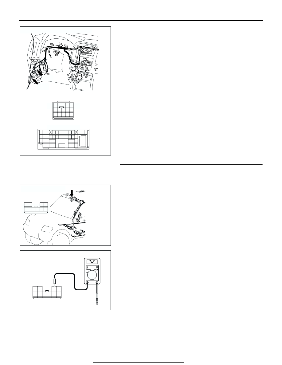
STEP 7. Check the ignition switch (IG2) circuit to the
sunroof motor assembly. Test at sunroof motor assembly
connector F-02.
(1) Disconnect sunroof motor assembly connector F-02 and
measure the voltage available at the wiring harness side of
the connector.
(2) Turn the ignition switch to the "ON" position.
(3) Measure the voltage between terminal 2 and ground.
• The voltage should be approximately 12 volts (battery
positive voltage).
Q: Is the measured voltage approximately 12 volts (battery
positive voltage)?
YES : Go to Step 10.
NO : Go to Step 8.
AC204188
CONNECTORS : D-26, D-28
D-28
AH
D-26
D-28
D-26
2 3
27
32
28
33
16
15
4 5
19
18
29
17
34
7 8
35
22
21
9 10
30
36
31
37
25
24
23
6
20
1
14
26
11
13
12
38
2 3
1
7
6
12
11
8
13
5
4
9 10
AC204177
CONNECTOR : F-02
AB
HARNESS SIDE
1
5
2
7
8
6
3
4
10 9
F-02
AC201740
5
1
7
8
6
2
9
10
4
3
AC
CONNECTOR: F-02
(HARNESS SIDE)