Mitsubishi Galant (2004+). Manual - part 786
COMPRESSOR ASSEMBLY AND TENSION PULLEY
TSB Revision
HEATER, AIR CONDITIONING AND VENTILATION
55A-283
INSTALLATION SERVICE POINT
.
>>A<< COMPRESSOR INSTALLATION
If a new compressor is installed, first adjust the amount of oil
according to the procedures described below, and then install
the compressor.
1. Measure the amount [X cm
3
(X fl.oz) of oil within the
removed compressor.
2. Drain (from the new compressor) the amount of oil
calculated according to the following formula, and then
install the new compressor.
New compressor oil amount = 140cm
2
(4.7 fl.oz)
140 cm
3
− X cm
3
= Y cm
3
(4.7 fl.oz.
− X fl.oz. = Y fl.oz)
NOTE: Y cm
3
(Y fl.oz) indicates the amount of oil in the refrig-
erant line, the condenser, the evaporator, etc.
NOTE: When replacing the following parts at the same times as
the compressor, subtract the rated oil amount of each part from
Y cm
3
(Y fl.oz) and discharge from the new compressor.
Quantity:
Evaporator: 60 cm
3
(2.0 fl.oz)
Condenser: 15 cm
3
(0.5 fl.oz)
Suction hose: 10 cm
3
(0.3 fl.oz)
Receiver: 10 cm
3
(0.3 fl.oz)
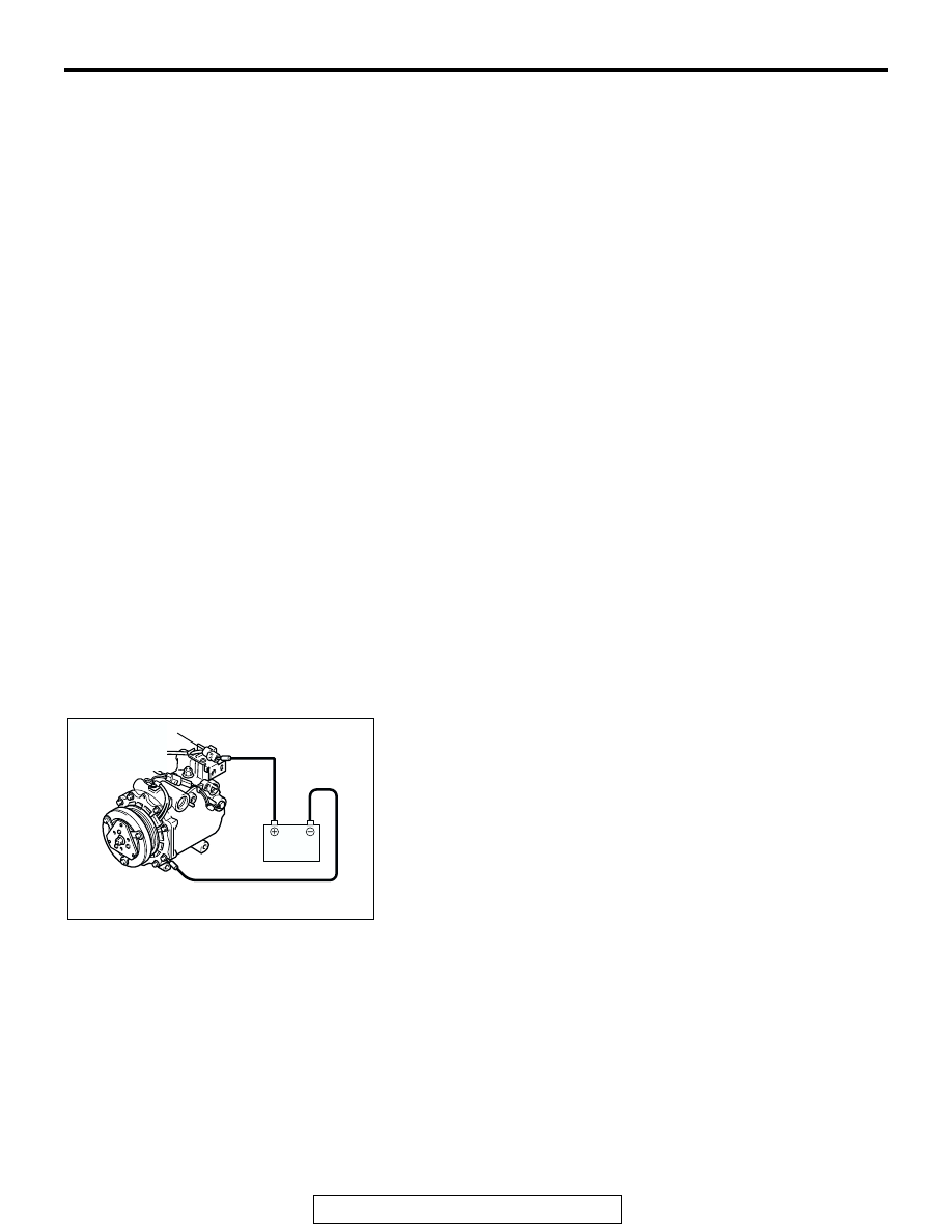
INSPECTION
M1552014301083
COMPRESSOR AIR CONDITIONING
COMPRESSOR CLUTCH OPERATION CHECK
Connect the compressor connector terminal to the battery posi-
tive (+) terminal and ground the battery’s negative (-) terminal
to the compressor unit. At that time, the air conditioning com-
pressor clutch should make a definite operating sound.
AC206292AB
A/C COMPRESSOR
CLUTCH
CONNECTOR