Mitsubishi Galant (2004+). Manual - part 784


  Index      Mitsubishi     Mitsubishi Galant - service repair manual 2004 year


Search            


Content   ..  782  783  784  785   ..


Mitsubishi Galant (2004+). Manual - part 784


HEATER UNIT, HEATER CORE, BLOWER ASSEMBLY AND EVAPORATOR UNIT

TSB Revision

HEATER, AIR CONDITIONING AND VENTILATION

55A-275

INSPECTION

M1552014301157

.

AIR MIXING DAMPER CONTROL MOTOR CHECK

CAUTION

Do not apply battery voltage when the damper is in the 
MAX COOL or MAX HOT position.
Check the air mix damper control motor by the following proce-
dures.

.

POTENTIOMETER CHECK
While checking the air mix damper control motor, measure the 
resistances between terminals numbers 3 and 5 and between 
numbers 3 and 7. At this time, the resistances should change 
gradually within the standard value.

Standard value: 1.7 (MAX HOT) 

 5.0 (MAX COOL) k

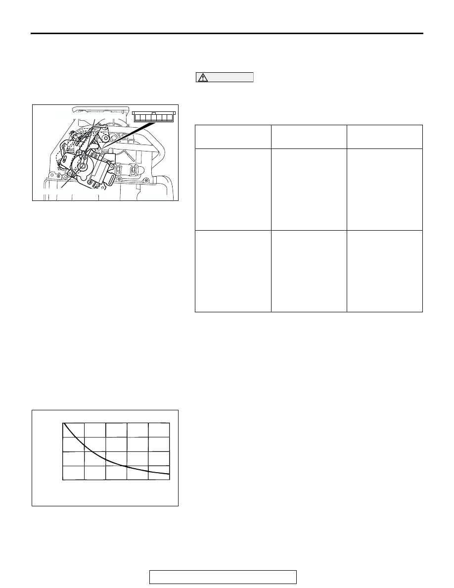
AIR THERMO SENSOR INSPECTION 

.

Measure the resistance between connector terminals 1 and 2 
under at least two different temperatures. The resistance val-
ues should generally match those in the graph. 
NOTE: The temperature at the check should not exceed the 
range in the graph. 

LEVER POSITION BATTERY 

CONNECTION

LEVER 
OPERATION

At the MAX COOL 
position

• Connect 

terminal 2 to the 
positive battery 
terminal

• Connect 

terminal 1 to the 
negative battery 
terminal

The lever moves 
from the MAX 
COOL position to 
the MAX HOT 
position

At the MAX HOT 
position

• Connect 

terminal 1 to the 
positive battery 
terminal

• Connect 

terminal 2 to the 
negative battery 
terminal

The lever moves 
from the MAX HOT 
position to the MAX 
COOL position

AC206296

MAX HOT POSITION

MAX COOL POSITION

1 2

4

3

5

7

6

AB

AC001043

RESISTANCE k

8

6

4

2

0

-10

0

 10

 20

 30

   40

TEMPERATURE ˚C(˚F)

AB

(14)

(32)

(50)

(86)

(104)

(68)

HEATER UNIT, HEATER CORE, BLOWER ASSEMBLY AND EVAPORATOR UNIT

TSB Revision

HEATER, AIR CONDITIONING AND VENTILATION

55A-276

BLOWER ASSEMBLY DISASSEMBLY AND ASSEMBLY

M1551005500209

AC306324

1

2

3

5

4

AB

DISASSEMBLY STEPS

1.

OUTSIDE/INSIDE AIR 
SELECTION DAMPER CONTROL 
MOTOR 

2.

RESISTOR <LOW TYPE> OR 
POWER TRANSISTOR <MIDDLE 
TYPE>

3.

BLOWER MOTOR

4.

BLOWER CASE UPPER

5.

BLOWER CASE LOWER

DISASSEMBLY STEPS 

MOTORS AND TRANSISTOR

TSB Revision

HEATER, AIR CONDITIONING AND VENTILATION

55A-277

MOTORS AND TRANSISTOR

REMOVAL AND INSTALLATION

M1551006900028

AC209768

AC306553

1

2

3

4

AB

MODE SELECTION DAMPER 
CONTROL MOTOR REMOVAL 
STEP

1.

MODE SELECTION DAMPER 
CONTROL MOTOR
POWER TRANSISTOR REMOVAL 
STEP

GLOVE BOX ASSEMBLY, 
INSTRUMENT CENTER PANEL 
ASSEMBLY (REFER TO GROUP 
52A, INSTRUMENT PANEL 

P.52A-3

).

2.

RESISTOR <LOW TYPE> OR 
POWER TRANSISTOR <MIDDLE 
TYPE>

BLOWER MOTOR REMOVAL 
STEP

3.

BLOWER MOTOR
OUTSIDE/INSIDE AIR 
SELECTION DAMPER MOTOR 
REMOVAL STEP

GLOVE BOX ASSEMBLY, 
INSTRUMENT CENTER PANEL 
ASSEMBLY (REFER TO GROUP 
52A, INSTRUMENT PANEL 

P.52A-3

).

4.

OUTSIDE/INSIDE AIR 
SELECTION DAMPER MOTOR

MOTORS AND TRANSISTOR

TSB Revision

HEATER, AIR CONDITIONING AND VENTILATION

55A-278

INSPECTION

M1551006300338

.

MODE SELECTION DAMPER CONTROL MOTOR CHECK

CAUTION

Do not apply battery voltage when the damper is in the 
FACE or DEF position.
Check the mode selection damper control motor by the follow-
ing procedures.

.

POTENTIOMETER CHECK
While checking the mode selection damper control motor, mea-
sure the resistances between terminal numbers 3 and 5 and 
between terminal numbers 3 and 7. At this time, the resis-
tances should change gradually within the standard value.

Standard value: 0.8 (DEF) 

 4.8 (FACE) k

.

LEVER POSITION BATTERY 

CONNECTION

LEVER 
OPERATION

At the FACE 
position

• Connect 

terminal 2 to the 
positive battery 
terminal

• Connect 

terminal 1 to the 
negative battery 
terminal

The lever moves 
from the FACE 
position to the DEF 
position

At the DEF position

• Connect 

terminal 1 to the 
positive battery 
terminal

• Connect 

terminal 2 to the 
negative battery 
terminal

The lever moves 
from the DEF 
position to the 
FACE position

AC209789

FACE POSITION

DEF POSITION

AB

1 2

4

3

5

7

6


Content   ..  782  783  784  785   ..