Mitsubishi Galant (2004+). Manual - part 785


  Index      Mitsubishi     Mitsubishi Galant - service repair manual 2004 year


Search            


Content   ..  783  784  785  786   ..


Mitsubishi Galant (2004+). Manual - part 785


MOTORS AND TRANSISTOR

TSB Revision

HEATER, AIR CONDITIONING AND VENTILATION

55A-279

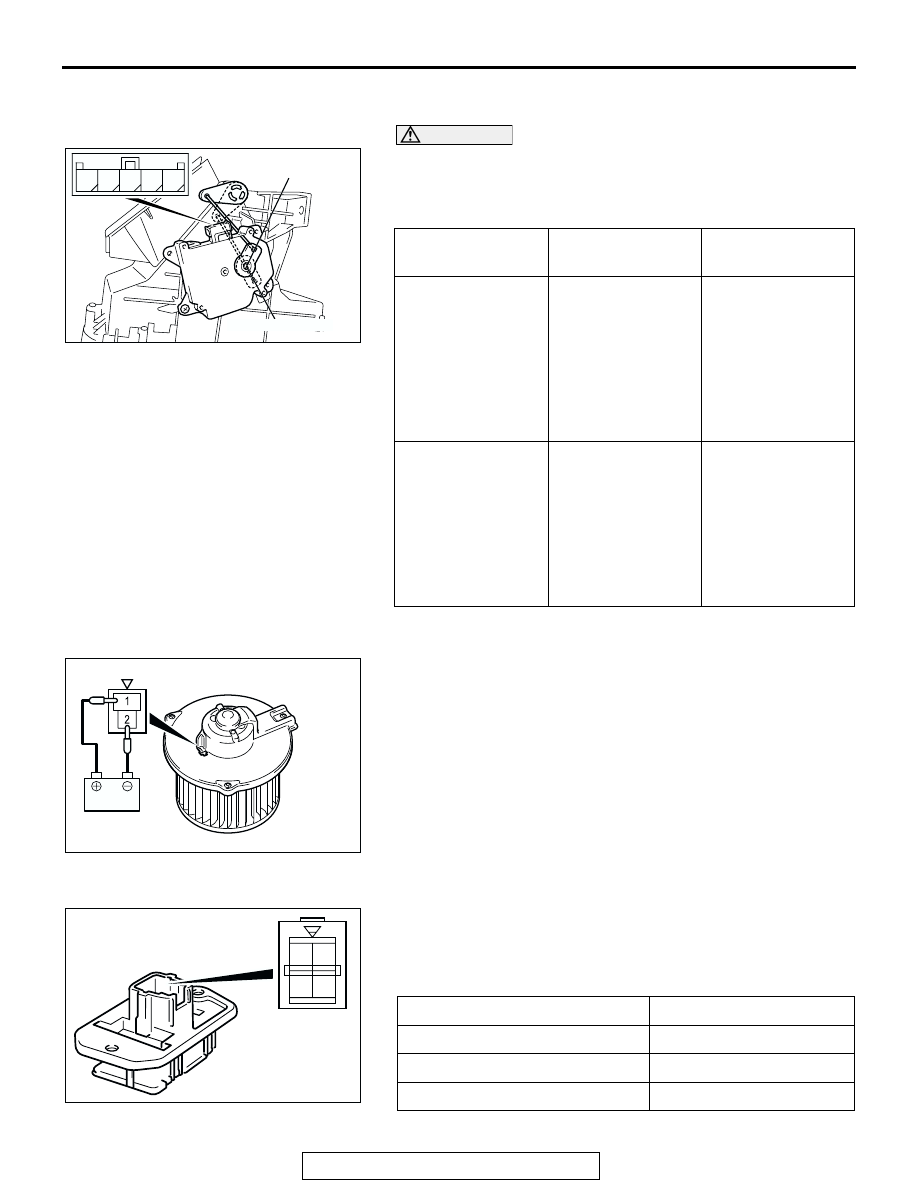
OUTSIDE/INSIDE AIR SELECTION DAMPER CONTROL 
MOTOR CHECK

CAUTION

Cut off the battery voltage when the damper is in the 
inside/outside air position.
Check the outside/inside air selection damper control motor by 
the following procedures.

.

BLOWER FAN AND MOTOR CHECK
When battery voltage is applied between the terminals, check 
that the motor operates. Also, check that there is no abnormal 
noise.

.

RESISTOR CHECK
Use an ohmmeter to measure the resistance between the ter-
minals. Check that the measured value is at the standard 
value.

Standard value:

LEVER POSITION BATTERY 

CONNECTION

LEVER 
OPERATION

At the inside 
position

• Connect 

terminal 1 to the 
positive battery 
terminal

• Connect 

terminal 5 to the 
negative battery 
terminal

The lever moves 
from the outside 
position to the 
inside position

At the outside 
position

• Connect 

terminal 1 to the 
positive battery 
terminal

• Connect 

terminal 4 to the 
negative battery 
terminal

The lever moves 
from the inside 
position to the 
outside position

AC206298

OUTSIDE POSITION

INSIDE POSITION

AB

3

1 2

4 5

AC209862

MEASUREMENT TERMINAL

STANDARD VALUE 

Between terminals 2 and 3 (LO)

2.79

Between terminals 1 and 2 (ML) 1.49

Between terminals 2 and 4 (MH) 0.39

AC307313

1 2

3 4

AMBIENT TEMPERATURE SENSOR

TSB Revision

HEATER, AIR CONDITIONING AND VENTILATION

55A-280

AMBIENT TEMPERATURE SENSOR

 REMOVAL AND INSTALLATION

M1554003400108

REMOVAL SERVICE POINT

.

<<A>> AMBIENT AIR TEMPERATURE SENSOR REMOVAL
Insert a screwdriver into the mounting hole of the front bumper 
core to release the clip, and remove the ambient temperature 
sensor.

AC306569

1

AB

REMOVAL STEP

FRONT BUMPER ASSEMBLY 
AND FRONT BUMPER CORE 
(REFER TO GROUP 51, FRONT 
BUMPER ASSEMBLY 

P.51-2

).

<<A>>

1.

AMBIENT AIR TEMPERATURE 
SENSOR

AC307252

AMBIENT AIR 
TEMPERATURE SENSOR

AB

SCREWDRIVER

FRONT BUMPER CORE

COMPRESSOR ASSEMBLY AND TENSION PULLEY

TSB Revision

HEATER, AIR CONDITIONING AND VENTILATION

55A-281

INSPECTION

M1551006300349

.

AMBIENT AIR TEMPERATURE SENSOR CHECK

CAUTION

The ambient air temperature sensor should be checked 
with removing it. If the sensor is removed, it is no longer 
serviceable.
Measure the resistance between the sensor terminals under at 
least two temperatures. The resistance values should meet the 
values shown.
NOTE: The temperature should be within the shown range.

COMPRESSOR ASSEMBLY AND TENSION PULLEY

REMOVAL AND INSTALLATION

M1552004100289

AC209942AB

REGISTANCE 
k

10

20

30

40

0

0

20

(32) (68)

TEMPERATURE ˚C (˚F)

40

(104)

60

(140)

-20

(-4)

-30

(-22)

Pre-removal Operation
• Refrigerant Discharging (Refer to 

P.55A-264

).

• Front Bumper Under Cover (Refer to GROUP 51, FRONT 

BUMPER

P.51-2

).

• Front Under Cover RH (Refer to GROUP 51, UNDER 

COVER 

P.51-11

).

Post-installation Operation
• Drive Belt Tension Adjustment (Refer to GROUP 00, 

Maintenance Service 

− Drive Belt 

P.00-43

).

• Refrigerant Charging (Refer to 

P.55A-264

).

• Front Bumper Under Cover (Refer to GROUP 51, FRONT 

BUMPER

P.51-2

).

• Front Under Cover RH (Refer to GROUP 51, UNDER 

COVER 

P.51-11

).

AC306575

1

AB

25 ± 4 N·m
18 ± 3 in-lb

2

3

N

4

5

7

1, 2

3

A/C compressor oil:
  SUN PAG 56

-Pipe coupling

<2.4 L ENGINE>

COMPRESSOR ASSEMBLY AND TENSION PULLEY

TSB Revision

HEATER, AIR CONDITIONING AND VENTILATION

55A-282

REMOVAL SERVICE POINTS

.

<<A>> FLEXIBLE SUCTION HOSE AND FLEXIBLE DIS-
CHARGE HOSE DISCONNECTION

CAUTION

As the compressor oil and receiver are highly moisture 
absorbent, use a non-porous material to plug the hose and 
nipples.
To prevent the entry of dust or other foreign bodies, plug the 
dismantled hoses and compressor nipples.

.

<<B>> COMPRESSOR REMOVAL
Take care not to spill any compressor oil when removing the 
compressor.

AC206183

N

1

2

3

4

5

6

AB

1, 2

3

A/C compressor oil:
  SUN PAG 56

-Pipe coupling

7

25 ± 4 N·m
18 ± 3 fi-lb

<3.8 L ENGINE>

REMOVAL STEPS

<<A>>

1.

FLEXIBLE SUCTION HOSE 
CONNECTION

<<A>>

2.

FLEXIBLE DISCHARGE HOSE 
CONNECTION

3.

O-RING

4.

DRIVE BELT

<<B>>

>>A<<

5.

A/C COMPRESSOR

6.

GENERATOR

7.

A/C COMPRESSOR BRACKET

REMOVAL STEPS (Continued)


Content   ..  783  784  785  786   ..