Mitsubishi Galant (2004+). Manual - part 159


  Index      Mitsubishi     Mitsubishi Galant - service repair manual 2004 year


Search            


Content   ..  157  158  159  160   ..


Mitsubishi Galant (2004+). Manual - part 159


CRANKSHAFT OIL SEAL

TSB Revision

ENGINE MECHANICAL <3.8L ENGINE>

11C-43

INSTALLATION SERVICE POINTS

.

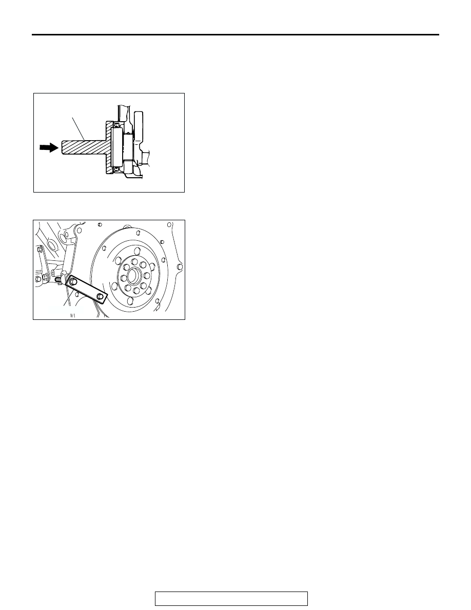
>>A<< CRANKSHAFT REAR OIL SEAL INSTALLATION
1. Apply a small amount of engine oil to the entire 

circumference of the oil seal lip.

2. Use special tool MD998718 to tap in the oil seal as shown in 

the illustration.

.

>>B<< DRIVE PLATE BOLTS INSTALLATION
Use special tool MD998781 in the same way as during removal 
to install the drive plate bolts.

ACX00356AB

MD998718

AC306686

MD998781

AB

CYLINDER HEAD GASKET

TSB Revision

ENGINE MECHANICAL <3.8L ENGINE>

11C-44

CYLINDER HEAD GASKET

REMOVAL AND INSTALLATION

M1112004000804

Pre-removal and Post-installation Operation
• Intake Manifold Removal and Installation (Refer to 

GROUP 15, Intake Manifold 

P.15-12

.)

• Exhaust Manifold Removal and Installation (Refer to 

GROUP 15, Exhaust Manifold 

P.15-17

.)

• Timing Belt Removal and Installation (Refer to 

P.11C-48

.)

• Thermostat Housing Removal and Installation (Refer to 

GROUP 14, Water Hose and Water Pipe 

P.14-24

.)

• Generator Removal and Installation (Refer to GROUP 16, 

Generator Assembly 

P.16-16

.)

AC306788

<COLD ENGINE>
108 ± 5 N·m
80 ± 3 ft-lb

108 ± 5 N·m
80 ± 3 ft-lb

(ENGINE OIL)

<COLD ENGINE>
108 ± 5 N·m
80 ± 3 ft-lb

108 ± 5 N·m
80 ± 3 ft-lb

(ENGINE OIL)

3.5 ± 0.5 N·m
31 ± 4 in-lb

10 ± 2 N·m
89 ± 17 in-lb

10 ± 2 N·m
89 ± 17 in-lb

3.5 ± 0.5 N·m
31 ± 4 in-lb

22 ± 4 N·m
16 ± 3 ft-lb

88 ± 10 N·m
65 ± 7 ft-lb

41 ± 8 N·m
30 ± 6 ft-lb

14 ± 1 N·m
120 ± 13 in-lb

1

2

3

4

5

6

7

8

9

10

11

12

13

14

15

16

17

18

19

20

21

22

23

N

N

N

N

AB

0 N·m
0 in-lb

0 N·m
0 in-lb

REMOVAL STEPS

1.

BLOW-BY HOSE CONNECTION

2.

PCV HOSE CONNECTION

3.

PCV VALVE

4.

IGNITION COIL CONNECTOR

5.

IGNITION COIL

6.

ENGINE CONTROL WIRING 
HARNESS CLAMP

7.

ROCKER COVER

8.

ROCKER COVER GASKET

REMOVAL STEPS (Continued)

CYLINDER HEAD GASKET

TSB Revision

ENGINE MECHANICAL <3.8L ENGINE>

11C-45

Required Special Tools:

• MD998051: Cylinder Head Bolt Wrench

• MB990767: End Yoke Holder

• MD998715: Crankshaft Pulley Holder Pin

REMOVAL SERVICE POINTS

.

<<A>> CAMSHAFT SPROCKET REMOVAL
Use special tools MD998715 and MB990767 to remove the 
camshaft sprocket.

.

9.

CAMSHAFT POSITION SENSOR 
CONNECTOR

10. GROUNDING

ENGINE OIL DIPSTICK 
ASSEMBLY

<<A>>

>>C<<

11. CAMSHAFT SPROCKET
12. TIMING BELT REAR CENTER 

COVER

<<B>>

>>B<<

13. LEFT BANK CYLINDER HEAD 

ASSEMBLY

14. CYLINDER HEAD GASKET

POWER STEERING OIL PUMP 
ASSEMBLY (REFER TO GROUP 
37A, POWER STEERING OIL 
PUMP ASSEMBLY 

P.37A-55

.)

15. POWER STEERING OIL PUMP 

BRACKET BOLT

16. IGNITION COIL CONNECTOR
17. IGNITION COIL
18. BREATHER HOSE CONNECTION
19. BLOW-BY HOSE CONNECTION
20. ROCKER COVER
21. ROCKER COVER GASKET

<<B>>

>>B<<

22. RIGHT BANK CYLINDER HEAD 

ASSEMBLY

>>A<<

23. CYLINDER HEAD GASKET

REMOVAL STEPS (Continued)

ACX00301AB

MB990767

MD998715

CYLINDER HEAD GASKET

TSB Revision

ENGINE MECHANICAL <3.8L ENGINE>

11C-46

<<B>> CYLINDER HEAD ASSEMBLY REMOVAL
Use special tool MD998051 to loosen each bolt two or three 
steps in the order shown in the illustration.

INSTALLATION SERVICE POINTS

.

>>A<< CYLINDER HEAD GASKET INSTALLATION
1. Degrease the cylinder head and cylinder block gasket 

mounting surfaces.

2. Make sure that the gasket has the proper identification mark 

for the engine.

3. Lay the cylinder head gasket on the cylinder block with the 

identification mark at the front top.

.

AC205273

AC206708

MD998051

EXHAUST SIDE

EXHAUST SIDE

INTAKE SIDE

RIGHT BANK

LEFT BANK

1

2

3

4

5

6

7

8

1

2

3

4

5

6

7

8

AB

ACX00349AB

IDENTIFICATION MARK


Content   ..  157  158  159  160   ..