Mitsubishi Galant (2004+). Manual - part 1429


  Index      Mitsubishi     Mitsubishi Galant - service repair manual 2004 year


Search            


Content   ..  1427  1428  1429  1430   ..


Mitsubishi Galant (2004+). Manual - part 1429


ON-VEHICLE SERVICE

TSB Revision

POWER STEERING

37A-25

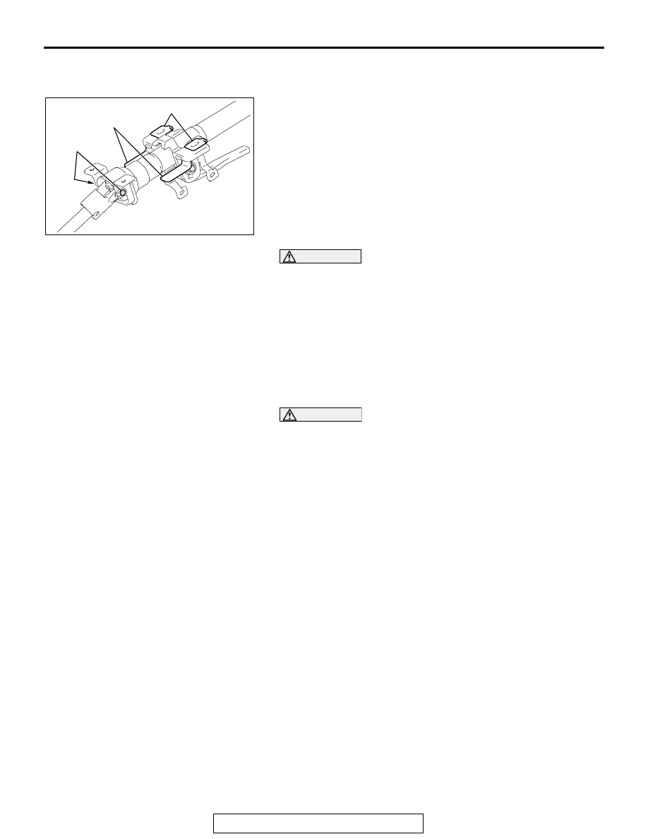
STEERING COLUMN SHAFT ASSEMBLY SHOCK 
ABSORBING MECHANISM CHECK

M1372013500131

• If a collision occurs or severe impact is applied to the steer-

ing wheel, the collision energy absorbing mechanism (slide 
plate, ripping plate, tilt pin) may have operated. Once the 
mechanism has operated, it will be inoperative even if there 
is no apparent damage. Determine if the steering column 
shaft can be reused by the following procedure. If the colli-
sion energy absorbing mechanism has already operated, 
replace the steering column assembly.

• If any excessive radial or axial free play on the steering 

wheel is found with the tilt lever in the lock position, always 
check the steering column assembly.

WARNING

1.

If the vehicle continues to be driven after the colli-
sion absorbing mechanism has operated, the 
steering column shaft may be damaged while driv-
ing.

2.

If there is a slack in the one-way capsule, do not 
attempt to repair it. Replace the steering column 
assembly.

Inspection Procedure

1. Remove the steering column covers (lower and upper).

CAUTION

Do not release the tilt lever until the steering column has 
been installed to complete this inspection procedure.
2. Place the tilt lever in the locked position.
3. Loosen the two upper steering column mounting bolts by 

two turns.

4. Hold the steering wheel, and then try to rock it. If there is a 

radial or axial free play, replace the steering column 
assembly.

AC308268 AC

SLIDE PLATE

RIPPING PLATE

TILT PIN

ON-VEHICLE SERVICE

TSB Revision

POWER STEERING

37A-26

5. Check the tilt pin fixing detent of the lower bracket for 

deformation. If there is a deformation, replace the steering 
column assembly.

CAUTION

• Be careful that nothing is pinched between the one-way 

capsules and the body.

• Do not release the tilt lever until the steering column 

has been installed to complete this inspection proce-
dure.

6. If no problem is found during the inspection, tighten the 

steering column assembly mounting bolts to the specified 
torque.

Tightening torque: 12 

± 2 Nm (102 ± 22 in-lb)

AC308269 AB

TILT PIN

DETENT

STEERING WHEEL

TSB Revision

POWER STEERING

37A-27

STEERING WHEEL

REMOVAL AND INSTALLATION

M1372011400224

WARNING

Before removing the steering wheel and air bag module assembly, refer to GROUP 52B, 
Service Precautions (

P.52B-26

) and Air Bag Module and Clock Spring (

P.52B-368

).

When removing and installing the steering wheel, do not let it bump against the air bag 
module.

NOTE: For air bag module removal, refer to GROUP 
52B, Air Bag Module and Clock Spring 

P.52B-368

.

Required Special Tool:

• MB990803: Steering Wheel Puller

Post-installation Operation
• Checking Steering Wheel Position with Wheels Straight 

Ahead

AC306560

41 ± 8 N·m
30 ± 6 ft-lb

1

3

4

6

9.0 ± 2.0 N·m
80 ± 17 in-lb

AB

N

3.9 ± 0.9 N·m
35 ± 8 in-lb

2

5

2

2

REMOVAL STEPS

1. STEERING WHEEL LOWER 

COVER

<<A>>

2. CONNECTORS (FOR HORN, AIR 

BAG MODULE, AND STEERING 
WHEEL REMOTE CONTROL 
HARNESS)

3. AIR BAG MODULE
4. STEERING WHEEL DYNAMIC 

DAMPER

5. STEERING WHEEL REMOTE 

CONTROL HARNESS

<<B>>

6. STEERING WHEEL ASSEMBLY

INSTALLATION STEPS

CLOCK SPRING MATING MARK 
ALIGNMENT (REFER TO GROUP 
52B, AIR BAG MODULE AND 
CLOCK SPRING 

P.52B-368

).

6. STEERING WHEEL ASSEMBLY

5. STEERING WHEEL REMOTE 

CONTROL HARNESS

4. STEERING WHEEL DYNAMIC 

DAMPER

3. AIR BAG MODULE
2. CONNECTORS (FOR HORN, AIR 

BAG MODULE, AND STEERING 
WHEEL REMOTE CONTROL 
HARNESS)

1. STEERING WHEEL LOWER 

COVER

INSTALLATION STEPS 

STEERING WHEEL

TSB Revision

POWER STEERING

37A-28

REMOVAL SERVICE POINTS

.

<<A>> CONNECTOR (FOR AIR BAG MODULE) REMOVAL
Slide the outer housing of the clock spring connector in the 
arrow direction shown, and disconnect the connector.

.

<<B>>STEERING WHEEL ASSEMBLY REMOVAL
Use special tool MB990803 to remove the steering wheel.

AC306561AB

OUTER HOUSING OF THE 
CLOCK SPRING CONNECTOR

AC000991AB

MB990803


Content   ..  1427  1428  1429  1430   ..