Content .. 1425 1426 1427 1428 ..
Mitsubishi Galant (2004+). Manual - part 1427
ON-VEHICLE SERVICE
TSB Revision
POWER STEERING
37A-17
ON-VEHICLE SERVICE
STEERING WHEEL FREE PLAY CHECK
M1372001000344
1. With the engine running (hydraulic operation), set the front
wheels straight ahead.
2. Slightly move the steering wheel in both directions and
measure the play on the steering wheel circumference
before the wheels start to move.
Limit: 30 mm (1.2 inch)
3. If the play exceeds the limit, check on the steering shaft and
steering linkage connection. Correct or replace.
4. If the free play still exceeds the limit value, set the steering
wheel straight ahead with the engine stopped. Apply 5 N
(1.1 pound) towards the steering wheel circumference and
check the play.
Standard value (steering wheel play with the engine
stopped): 10 mm (0.4 inch) or less
5. If the play exceeds the standard value, remove the steering
) and check the total pinion torque
(refer to
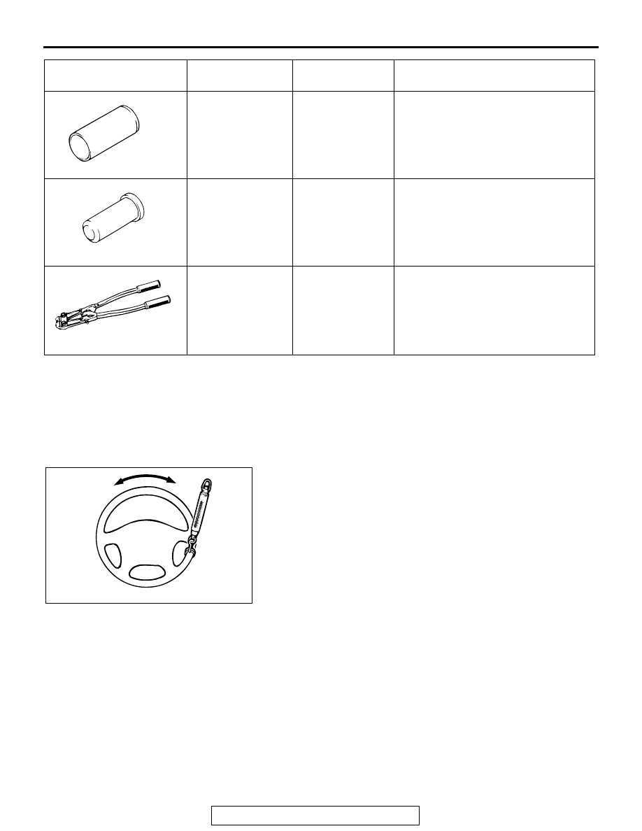
MB991317
Seal ring installer
Tool not available Seal ring installation
MB991152
Dust cover installer
General service
tool
Oil seal installation
MB991561
Boot band crimping
tool
MB991561
Bellows band installation
TOOL
TOOL NUMBER
AND NAME
SUPERSESSION APPLICATION
MB991317
MB991152
MB991561
ACX01122 AB