Mitsubishi Galant (2004+). Manual - part 1428


  Index      Mitsubishi     Mitsubishi Galant - service repair manual 2004 year


Search            


Content   ..  1426  1427  1428  1429   ..


Mitsubishi Galant (2004+). Manual - part 1428


ON-VEHICLE SERVICE

TSB Revision

POWER STEERING

37A-21

FLUID LEVEL CHECK

M1372002000303

1. Park the vehicle on a flat, level surface.
2. Start the engine, and then turn the steering wheel several 

times to raise the temperature of the fluid to approximately 
50 

− 60°C (122 − 140°F).

3. With the engine running, turn the wheel all the way to the left 

and right several times.

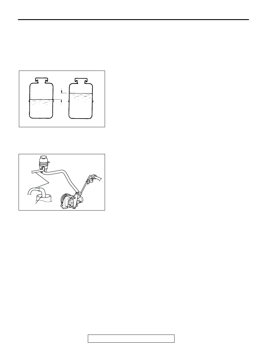
4. Check the fluid in the oil reservoir for foaming or milkiness. 

Check the difference of the fluid level when the engine is 
stopped, and while it is running. If the fluid contains air or 
has milky appearance, or the fluid level fluctuate by 5 mm 
(0.2 inch) or more, power steering system air bleeding 
should be done.

FLUID REPLACEMENT

M1372002100366

1. Raise and support the front wheels.
2. Disconnect the return hose connection, and then connect a 

vinyl hose to the return hose, and drain the fluid into a 
container.

3. Disconnect the ignition coil connectors (refer to GROUP 16, 

Ignition Coil 

P.16-40

 <2.4L ENGINE>, 

P.16-41

 <3.8L 

ENGINE>).

4. While operating the starter motor intermittently, turn the 

steering wheel all the way to the left and right several times 
to drain all of the fluid.

5. Connect the return hose securely, and then secure with the 

clip.

6. Fill the oil reservoir with GENUINE MITSUBISHI POWER 

STEERING FLUID up to the lower mark of the reservoir, and 
then bleed the air.

ACX01131

WHILE ENGINE
RUNNING

AC

FLUID LEVEL CHANGE:WITHIN 5 mm (0.2 in)

WHILE ENGINE
STOPPED

AC206743

RETURN
HOSE

VINYL HOSE

AB

ON-VEHICLE SERVICE

TSB Revision

POWER STEERING

37A-22

POWER STEERING SYSTEM AIR BLEEDING

M1372002200352

Perform air bleeding procedure as necessary after replacing 
the steering gear, oil pump or the steering fluid lines.
1. Raise and support the front wheels.
2. Disconnect the ignition coil connectors (Refer to GROUP 16, 

Ignition Coil 

P.16-40

 <2.4L ENGINE>, 

P.16-41

 <3.8L 

ENGINE>).

CAUTION

Perform air bleeding only while cranking the engine. Do 
not perform air bleeding while the engine is running. If you 
do so, air in the fluid will be increased and air bleeding will 
become more difficult. During air bleeding, refill the steer-
ing fluid so that the level never falls below the lower mark 
on the dipstick.
3. Turn the steering wheel all the way to the left and right five 

or six times while using the starter motor to crank the engine 
intermittently several times (for 15 to 20 seconds).

4. Connect the ignition coil connectors (Refer to GROUP 16, 

Ignition Coil 

P.16-40

 <2.4L ENGINE>, 

P.16-41

 <3.8L 

ENGINE>).

5. Start the engine and allow to idle.
6. Turn the steering wheel to the left and right until there are no 

air bubbles in the oil reservoir.

7. Confirm that the fluid is not milky, and that the level is 

between the high and low dipstick marks.

8. Confirm that there is very little change in the fluid level when 

the steering wheel is turned left and right.

CAUTION

If the fluid level rises suddenly after the engine is stopped, 
the air has not been completely bled. If air bleeding is not 
complete, there will be abnormal noises from the pump 
and the flow-control valve, and this condition could reduce 
the life of the power steering components.
9. Confirm that the change in the fluid level is no more than 5 

mm (0.2 inch) when the engine is stopped.

10.If the change of the fluid level is 5 mm (0.2 inch) or more, 

the air has not been completely bled from the system. The 
air bleeding procedure must be repeated.

ACX01131

WHILE ENGINE
RUNNING

AC

FLUID LEVEL CHANGE:WITHIN 5 mm (0.2 in)

WHILE ENGINE
STOPPED

ON-VEHICLE SERVICE

TSB Revision

POWER STEERING

37A-23

OIL PUMP PRESSURE TEST

M1372002300337

Required Special Tools:

• MB990662: Power Steering Oil Pressure Gauge

• MB991548: Power Steering Oil Pressure Gauge Adapter 

(Pump Side)

• MB991549: Power Steering Oil Pressure Gauge Adapter 

(Hose Side)

1. Disconnect the pressure hose from the oil pump, and then 

connect special tools MB991548, MB990662 and 
MB991549.

2. Bleed air, then turn the steering wheel several times while 

the vehicle is not moving so that the temperature of the fluid 
rises to approximately 50 

− 60°C (122 − 140°F).

3. Start the engine and idle it.

CAUTION

The pressure gauge shut-off valve must not remain closed 
for more than 10 seconds.
4. Fully close the shut-off valve of the pressure gauge and 

measure the oil pump relief pressure to confirm that it is 
within the standard value range. Open it again immediately 
after checking the pressure.

Standard value:

2.4L engine: 8.3 

 8.8 MPa (1,204  1,276 psi)

3.8L engine: 9.3 

 9.8 MPa (1,349  1,421 psi)

5. If it is not within the standard value, replace the oil pump.
6. Check whether or not the hydraulic pressure is the standard 

value when no-load conditions are created by fully opening 
the shut-off valve of the pressure gauge.

Standard value: 0.8 

 1.0 MPa (116  145 psi)

7. If it is not within the standard value, the probable cause is a 

malfunction of the oil line or steering gear, so check these 
parts and repair as necessary.

8. Turn the steering wheel all the way to the left or right; then 

check the retention hydraulic pressure.

Standard value:

2.4L engine: 8.3 

 8.8 MPa (1,204  1,276 psi)

3.8L engine: 9.3 

 9.8 MPa (1,349  1,421 psi)

9. If not the standard value, overhaul or replace the steering 

gear. Remeasure fluid pressure.

10. Remove special tools MB991548, MB990662 and 

MB991549, connect the pressure hose to the oil pump, and 
then tighten the eye bolt to the specified torque.

Tightening torque: 57 

± 7 Nm (42 ± 5 ft-lb)

11. Bleed the system (Refer to 

P.37A-22

).

ACX01133

THERMO-
METER

RESERVOIR

ADAPTER
(MB991548)

OIL
PUMP

ADAPTER
(MB991549)

AB

SHUT-OFF VALVE
(FULLY CLOSED)

PRESSURE
GAUGE
(MB990662)

ON-VEHICLE SERVICE

TSB Revision

POWER STEERING

37A-24

POWER STEERING PRESSURE SWITCH CHECK

M1372007200346

Required Special Tools:

• MB990662: Power Steering Oil Pressure Gauge

• MB991548: Power Steering Oil Pressure Gauge Adapter 

(Pump Side)

• MB991549: Power Steering Oil Pressure Gauge Adapter 

(Hose Side)

1. Disconnect the pressure hose from the oil pump, and then 

connect the special tools MB991548, MB990662 and 
MB991549.

2. Bleed air, and then turn the steering wheel several times 

while the vehicle is not moving so that the temperature of 
the fluid rises to approximately 50 

− 60°C (122 − 140°F).

3. The engine should be idling.
4. Disconnect the connector for the oil pressure switch, and 

place an ohmmeter at the switch.

5. Gradually close the shut-off valve of the pressure gauge and 

increase the hydraulic pressure, then check whether or not 
the hydraulic pressure that activates the switch is the 
standard value.

Standard value: 1.8 

 2.4 MPa (261  348 psi)

6. Gradually open the shut-off valve and reduce the hydraulic 

pressure; then check whether or not the hydraulic pressure 
that deactivates the switch is the standard value.

Standard value: 0.8 

 2.4 MPa (116  348 psi)

7.  Remove special tools MB991548, MB990662 and 

MB991549, connect the pressure hose to the oil pump, and 
then tighten the eye bolt to the specified torque.

Tightening torque: 57 

± 7 Nm (42 ± 5 ft-lb)

8. Bleed the system. (Refer to 

P.37A-22

).

TIE ROD END BALL JOINT DUST COVER CHECK

M1372008600284

1. Press the dust cover with your finger to check whether the 

dust cover is cracked or damaged.

2. If the dust cover is cracked or damaged, replace the tie rod 

end.
NOTE: If the dust cover is cracked or damaged, the ball joint 
could be damaged.

ACX01134 AB

THERMO-
METER

ADAPTER
(MB991548)

RESERVOIR

OIL
PUMP

ADAPTER
(MB991549)

SHUT-OFF
VALVE

PRESSURE
GAUGE
(MB990662)


Content   ..  1426  1427  1428  1429   ..