Mitsubishi Galant (2004+). Manual - part 135
ON-VEHICLE SERVICE
TSB Revision
ENGINE MECHANICAL <2.4L ENGINE>
11A-13
CAUTION
To prevent damage to scan tool MB991958, always turn the
ignition switch to the "LOCK" (OFF) position before con-
necting or disconnecting scan tool MB991958.
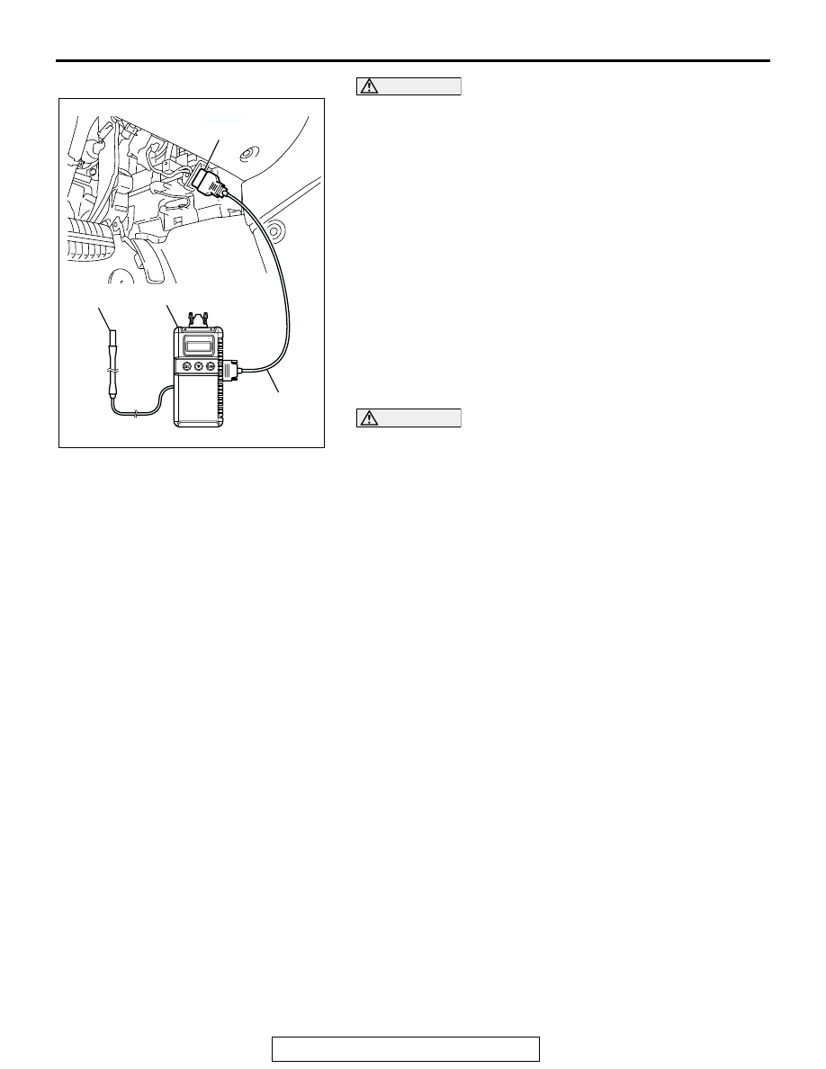
2. Connect scan tool MB991958 to the data link connector.
3. Set up a timing light.
4. Start the engine and run it at idle.
5. Check that the idle speed is approximately 700 r/min.
6. Select scan tool MB991958 actuator test "item number 17".
7. Check that basic ignition timing is within the standard value.
Standard value: 5
° BTDC ± 3°
8. If the basic ignition timing is not within the standard value,
check the following items:
• Diagnostic output
• Timing belt cover and crankshaft position sensor installation
conditions
• Crankshaft sensing blade condition
CAUTION
If the actuator test is not canceled, the forced drive will
continue for 27 minutes. Driving in this state could lead to
engine failure.
9. Press the clear key on scan tool MB991958 (select forced
drive stop mode), and cancel the actuator test.
10.Check that the actual ignition timing is at the standard value.
Standard value: Approximately 10
° BTDC
NOTE: Ignition timing fluctuates about
±
7
°
Before Top Dead
Center, even under normal operating condition.
NOTE: It is automatically further advanced by about 5
°
to
10
°
Before Top Dead Center at higher altitudes.
CURB IDLE SPEED CHECK
M1111003500568
Required Special Tool:
MB991958: Scan Tool (MUT-III Sub Assembly)
• MB991824: V.C.I.
• MB991827: MUT-III USB Cable
• MB991910: MUT-III Main Harness A
1. Before checks, set the vehicle in the following condition.
• Engine coolant temperature: 80 − 95°C (176 − 203°F)
• Lights and all accessories: OFF
• Transaxle: P range
NOTE: Vehicles for Canada, the headlight, taillight, etc.
remain lit even when the lighting switch is in "OFF" position
but this is no problem for checks.
AC302077
AC305412
AC306958AB
MB991824
MB991910
MB991668
DATA LINK
CONNECTOR