Mitsubishi Galant (2004+). Manual - part 134


  Index      Mitsubishi     Mitsubishi Galant - service repair manual 2004 year


Search            


Content   ..  132  133  134  135   ..


Mitsubishi Galant (2004+). Manual - part 134


ON-VEHICLE SERVICE

TSB Revision

ENGINE MECHANICAL <2.4L ENGINE>

11A-9

CAUTION

To prevent damage to scan tool MB991824, always turn the 
ignition switch to the "LOCK" (OFF) position before con-
necting or disconnecting scan tool MB991824.

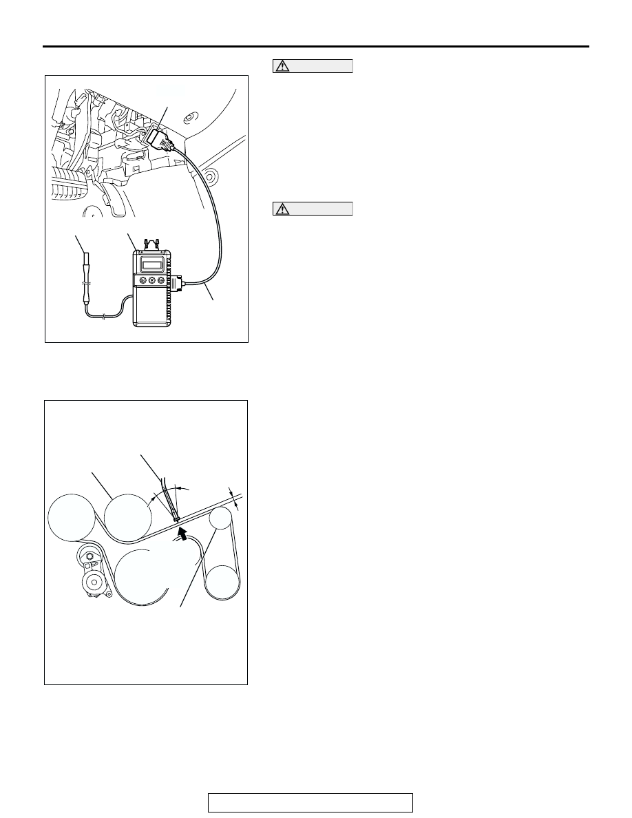
(1) Connect special tool MB991668 to scan tool MB991824.
(2) Connect scan tool MB991910 to scan tool MB991824.
(3) Connect scan tool MB991910 to the data link connector.
(4) Turn the ignition switch to the "ON" position and select 

"Belt Tension" from the menu scan tool MB991824 
screen.

CAUTION

• The temperature of the surface of the belt should be as 

close to normal temperature as possible.

• Do not allow any contaminants such as water or oil to 

get onto the microphone.

• If strong gusts of wind blow against the microphone or 

if there are any loud sources of noise nearby, the val-
ues measured by the microphone may not correspond 
to actual values.

• If the microphone is touching the belt while the mea-

surement is being made, the values measured by the 
microphone may not correspond to actual values.

• Do not take the measurement while the vehicle's engine 

is running.

(5) Hold special tool MB991668 to the middle of the drive 

belt between the pulleys (at the place indicated by arrow), 
approximately 10 

− 20 mm (0.40 − 0.78 inch) away from 

the rear surface of the belt so that it is perpendicular to 
the belt (within an angle of 

± 15 degree).

(6) Gently tap the middle of the belt between the pulleys (the 

place indicated by the arrow) with your finger as shown in 
the illustration, and measure that the vibration frequency 
of the belt is within the standard value.

Standard value: 120 

 154 Hz

3. If not within the standard value, replace the auto-tensioner. 

(Refer to 

P.11A-49

).

.

AC302077
AC305412

AC306958AB

MB991824

MB991910

MB991668

DATA LINK

CONNECTOR

AC301266AB

MB991668

10 – 20 mm
(0.40 – 0.78 in)

WATER 
PUMP 
PULLEY

GENTLY 
TAP WITH
YOUR 
FINGER

15˚

15˚

GENERATOR 
PULLEY

ON-VEHICLE SERVICE

TSB Revision

ENGINE MECHANICAL <2.4L ENGINE>

11A-10

When using a tension gauge
1. Check the drive belt tension. (Refer to 

P.11A-8

).

2. Use a belt tension gauge in the middle of the belt between 

the pulleys (at the place indicated by the arrow) to measure 
that the belt tension is within the standard value.

Standard value: 340 

 562 N

3. If not within the standard value, replace the auto-tensioner. 

(Refer to 

P.11A-49

).

VALVE CLEARANCE CHECK AND ADJUSTMENT

M1111001500119

1. Before checks, check that the engine oil, starter and battery 

are normal. Also, set the vehicle in the following condition:

• Engine coolant temperature: 80 − 95°C (176 − 203°F)

• Lights and all accessories: OFF

• Transaxle: P range

NOTE: Vehicles for Canada, the headlight, taillight, etc. 
remain lit even when the lighting switch is in "OFF" position 
but this is no problem for checks and adjustment.

2. Remove all of the ignition coils.
3. Remove the rocker cover.
4. Turn the crankshaft clockwise until the notch on the pulley is 

lined up with "T" mark on the timing indicator.

5. Move the rocker arms on the No.1 and No.4 cylinders up 

and down by hand to determine which cylinder has its piston 
at the top dead center on the compression stroke. 
If both intake and exhaust valve rocker arms have a valve 
lash, the piston in the cylinder corresponding to these rocker 
arms is at the top dead center on the compression stroke.

6. Valve clearance inspection and adjustment can be 

performed on rocker arms indicated by white arrow mark 
when the No.1 cylinder piston is at the top dead center on 
the compression stroke, and on rocker arms indicated by 
black arrow mark when the No.4 cylinder piston is at the top 
dead center on the compression stroke.

AC301267

BELT TENSION 
GAUGE

AB

GENERATOR 
PULLEY

WATER PUMP 
PULLEY

AK204362AD

EXHAUST VALVE SIDE

No. 1 No. 2 No. 3 No. 4

INTAKE VALVE SIDE

ON-VEHICLE SERVICE

TSB Revision

ENGINE MECHANICAL <2.4L ENGINE>

11A-11

7. Measure the valve clearance.

If the valve clearance is not as specified, loosen the rocker 
arm lock nut and adjust the clearance using a thickness 
gauge while turning the adjusting screw.

Standard value (hot engine):

<VEHICLES EXCEPT FOR CALIFORNIA EMISSION 

REGULATION>

Intake valve: 0.20 mm (0.008 inch)
Exhaust valve: 0.32 mm (0.013 inch)

<VEHICLES FOR CALIFORNIA EMISSION REGULA-

TION>

Intake valve: 0.20 mm (0.008 inch)
Exhaust valve: 0.31 mm (0.012 inch)

8. While holding the adjusting screw with a screwdriver to 

prevent it from turning, tighten the lock nut to the specified 
torque.

Tightening torque: 9 

± 1 Nm (80 ± 9 in-lb)

9. Turn the crankshaft through 360 degree angle to line up the 

notch on the crankshaft pulley with the "T" mark on the 
timing indicator.

10.Repeat steps (7) and (8) on other valves for clearance 

adjustment.

11.Install the rocker cover.
12.Install the ignition coils.

ROCKER ARM PISTON OPERATION CHECK

M1111051000012

1. Remove all of the ignition coils.
2. Remove the rocker cover.
3. Remove the engine oil control valve.
4. Remove the engine oil pressure switch.
5. Turn the crankshaft clockwise until the notch on the 

crankshaft pulley is lined up with "T" mark on the lower cover 
of timing belt.

6. Move the rocker arms on the No.1 and No.4 cylinders up 

and down by hand to determine which cylinder has its piston 
at the top dead center on the compression stroke. 

NOTE: The rocker arm piston operation check can be per-
formed on rocker arms indicated by white arrow mark when the 
No.1 cylinder piston is at the top dead center on the compres-
sion stroke, and on rocker arms indicated by black arrow mark 
when the No.4 cylinder piston is at the top dead center on the 
compression stroke.

AK302683AB

ENGINE OIL 
PRESSURE SWITCH
ENGINE OIL 
CONTROL VALVE

IGNITION COILS

ROCCER COVER

AK204362AH

EXHAUST VALVE SIDE

No. 1 No. 2 No. 3 No. 4

INTAKE VALVE SIDE

ON-VEHICLE SERVICE

TSB Revision

ENGINE MECHANICAL <2.4L ENGINE>

11A-12

7. While shutting up the oil passage hole at the depth of the 

engine oil control valve's installation hole by finger not to 
leak air, blow compression air into the engine oil pressure 
switch's installation hole by air blowgun. At this time, confirm 
that the rocker arm piston can operate.

NOTE: To fully confirm the check, prevent the compression air 
from leaking as much as possible by installing the O-ring to the 
end of air blowgun.
8. Turn the crankshaft clockwise until the notch on the 

crankshaft pulley is lined up with "T" mark on the lower cover 
of timing belt.

9. Confirm the rest of the rocker arm pistons under the 

procedure 7.

10.When the rocker arm piston does not operate, replace the 

rocker arm assy.

11.Install the engine oil pressure switch.
12.Install the engine oil control valve. (Refer to Camshaft and 

Valve Stem Seal 

− Removal and Installation 

P.11A-28

.)

13.Install all of the ignition coils.
14.Install the rocker cover.

IGNITION TIMING CHECK

M1111001700492

Required Special Tool:
MB991958: Scan Tool (MUT-III Sub Assembly)

• MB991824: V.C.I.

• MB991827: MUT-III USB Cable

• MB991910: MUT-III Main Harness A

1. Before checks, set the vehicle in the following condition:

• Engine coolant temperature: 80 − 95°C (176 − 203°F)

• Lights and all accessories: OFF

• Transaxle: P range

NOTE: Vehicles for Canada, the headlight, taillight, etc. 
remain lit even when the lighting switch is in "OFF" position 
but this is no problem for checks.

AK302864AB

ROCKER ARM 
PISTON

BLOW 
COMPRESSION 
AIR

OIL PASSAGE

ROCCER 
ARM


Content   ..  132  133  134  135   ..