Mitsubishi Galant. Manual - part 588


  Index      Mitsubishi     Mitsubishi Galant - service repair manual 2001 year


Search            


Content   ..  586  587  588  589   ..


Mitsubishi Galant. Manual - part 588


FRONT SEAT ASSEMBLY

TSB Revision

INTERIOR

52A-17

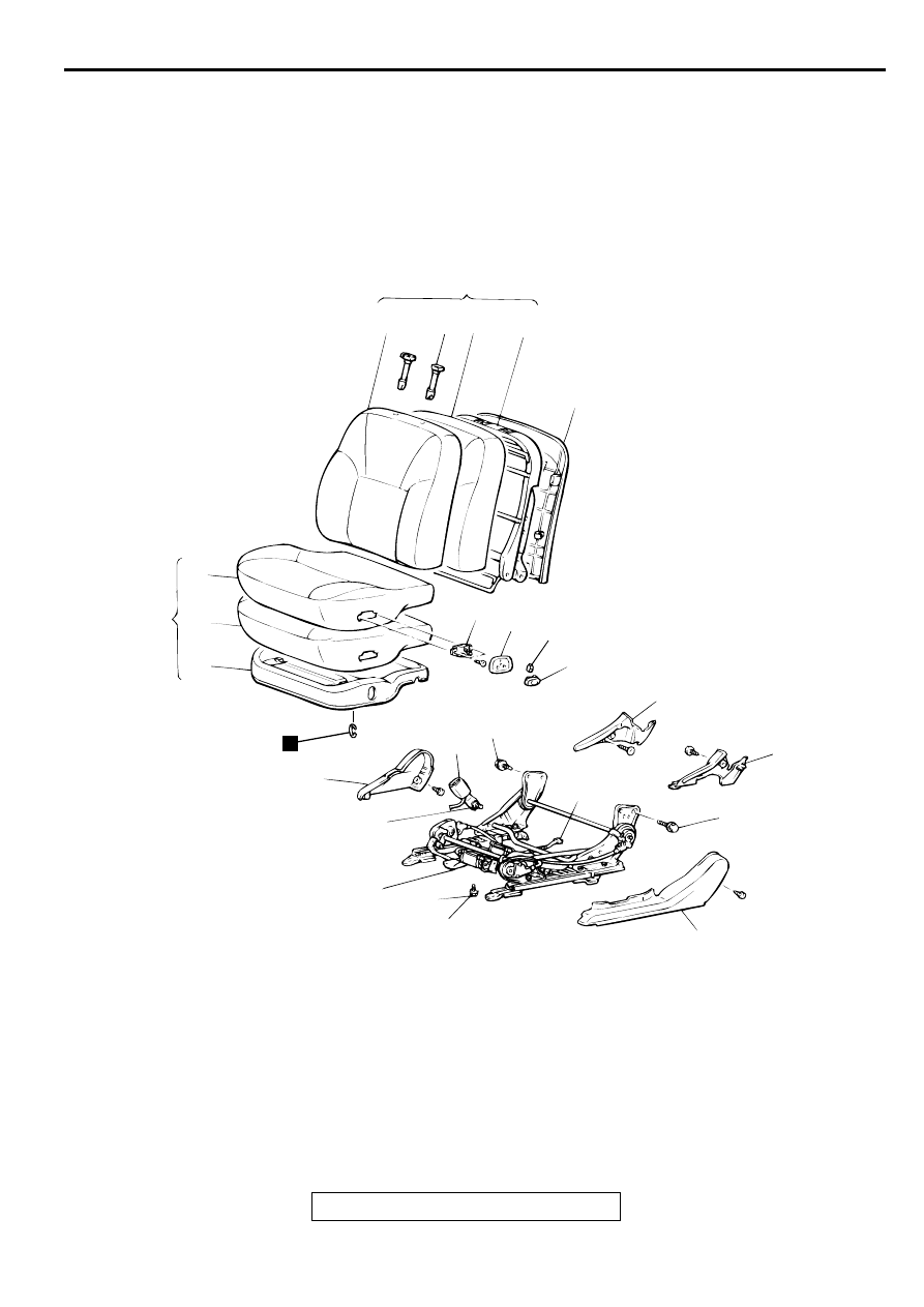
16. FRONT SEATBACK FRAME 

<VEHICLES WITHOUT SRS SIDE 
AIR BAG>

17. FRONT SEAT INNER COVER
18. FRONT SEAT INNER COVER
19. FRONT SEAT ADJUSTER 

ASSEMBLY

DISASSEMBLY STEPS (Continued)

AC003665AB

1

2

3

4

5

6

7

8

9

10

11

12

13

14

15

16

17

18

19

20

21

22

44 N·m
33 ft-lb

12 N·m
106 in-lb

22 N·m
16 ft-lb

22 N·m
16 ft-lb

N

<POWER SEAT>

DISASSEMBLY STEPS

1. FRONT SEAT SHIELD COVER
2. FRONT SEAT SHIELD COVER
3. INNER SEAT BELT
4. BOLT
5. FRONT SEAT CUSHION ASSEMBLY
6. FRONT SEAT RECLINING 

ADJUSTER LEVER

7. FRONT SEAT SLIDE ADJUSTER 

LEVER

8. GARNISH
9. POWER SEAT SWITCH

10. FRONT SEAT CUSHION COVER
11. FRONT SEAT CUSHION PAD
12. FRONT SEAT CUSHION FRAME

<<A>>

13. FRONT SEATBACK PANEL
14. FRONT SEATBACK ASSEMBLY 
15. HEADRESTRAINT GUIDE 
16. FRONT SEATBACK COVER
17. FRONT SEATBACK PAD
18. FRONT SEATBACK FRAME 

<VEHICLES WITHOUT SRS SIDE 
AIR BAG>

DISASSEMBLY STEPS (Continued)

FRONT SEAT ASSEMBLY

TSB Revision

INTERIOR

52A-18

DISASSEMBLY SERVICE POINT

<<A>> FRONT SEATBACK PANEL REMOVAL
1. Using a screwdriver or similar tool, push in the clip of the 

front seatback panel lower portion to remove it. 

2. Pull down the front seatback panel to remove it.

INSPECTION

M1522001600044

POWER SEAT SWITCH CONTINUITY CHECK

POWER SEAT MOTOR OPERATION CHECK
Inspect the operation of each motor according to the following 
procedures.
1. Disconnect the connector for each motor.

19. FRONT SEAT INNER COVER
20. FRONT SEAT INNER COVER
21. POWER SEAT HARNESS
22. POWER SEAT ADJUSTER 

ASSEMBLY

DISASSEMBLY STEPS (Continued)

AC000337AB

CLIP

FRONT SEATBACK PANEL

AC003150AB

RECLINING
SWITCH

SLIDE AND
HEIGHT SWITCH

SWITCH POSITION

TESTER CONNECTION SPECIFIED CONDITION

Reclining switchForward

3

13, 4

14

Continuity

Backward

3

14, 4

13

Continuity

Slide switchForward

8

13, 7

14

Continuity

Back ward

7

13, 8

14

Continuity

Front height switch

Up

5

14, 6

13

Continuity

Down

5

13, 6

14

Continuity

Rear height switch

Up

1

13, 2

14

Continuity

Down

1

14, 2

13

Continuity

All switches

OFF

No continuity

REAR SEAT ASSEMBLY

TSB Revision

INTERIOR

52A-19

2. When the battery is connected directly to the motor 

terminals, check if the motors run smoothly, and check if 
each setting mechanism runs in the direction shown in the 
table below for each motor.

(1) Connect the battery power source to the terminal 3 and 

ground the terminal 4 for the front/rear height down side 
and connect the battery power source to the terminal 4 
and ground the terminal 3 for the front/rear height up 
side.

(2) Connect the battery power source to the terminal 1 and 

ground the terminal 2 for the slide backward side and 
connect the battery power source to the terminal 2 and 
ground the terminal 1 for the slide forward side.

(3) Connect the battery power source to the terminal 2 and 

ground the terminal 1 for the reclining backward side and 
connect the battery power source to the terminal 1 and 
ground the terminal 2 for the reclining forward side.

3. If there is an abnormality, replace the power seat adjuster 

assembly.

REA R  SEAT ASSEM B LY

REMOVAL AND INSTALLATION

M1522001800071

AC003151AB

RECLINING MOTOR
CONNECTOR

REAR HEIGHT
MOTOR CONNECTOR

SLIDE MOTOR
CONNECTOR

FRONT HEIGHT
MOTOR
CONNECTOR

AC003152AB

1

2

1

2

22 N·m
16 ft-lb

22 N·m
16 ft-lb

22 N·m
16 ft-lb

22 N·m
16 ft-lb

22 N·m
16 ft-lb

<VEHICLES WITHOUT PARTIAL
TRUNK OPENING>

<VEHICLES WITH PARTIAL
TRUNK OPENING>

NOTE
      : Hook position

REMOVAL STEPS

<<A>>

1. REAR SEAT CUSHION 

>>A<<

2. REAR SEATBACK

REAR SEAT ASSEMBLY

TSB Revision

INTERIOR

52A-20

REMOVAL SERVICE POINT

<<A>> REAR SEAT CUSHION REMOVAL
While pulling the rear seat stopper pulled, lift up the seat 
cushion to remove it.

INSTALLATION SERVICE POINT

<<A>> REAR SEATBACK INSTALLATION
Push the seatback in the direction indicated in the illustration; 
then securely attach the attachment wire to the body side hook 
and install the seatback.

DISASSEMBLY AND ASSEMBLY

M1522002000089

AC000341AB

REAR SEAT STOPPER

AC003153AB

SEATBACK

ATTACHMENT
WIRE

HOOK

AC003154

1

2

3

4

1

2

3

4

5

6

7

8

AB

N

N

N

N

<VEHICLES WITHOUT PARTIAL
TRUNK OPENING>

<VEHICLES WITH PARTIAL
TRUNK OPENING>


Content   ..  586  587  588  589   ..