Mitsubishi Galant. Manual - part 514


  Index      Mitsubishi     Mitsubishi Galant - service repair manual 2001 year


Search            


Content   ..  512  513  514  515   ..


Mitsubishi Galant. Manual - part 514


REAR DISC BRAKE ASSEMBLY

TSB Revision

BASIC BRAKE SYSTEM

35A-47

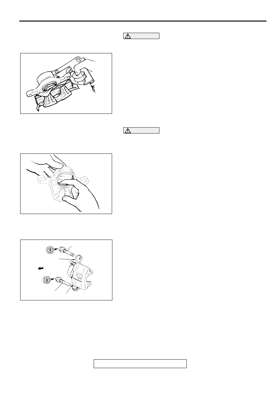
<<A>> PISTON BOOT/PISTON REMOVAL

CAUTION

Blow air little by little to remove the piston. The piston will 
rush out if a force of air is applied suddenly.
Place a piece of wood, etc. against the caliper body as shown. 
Blow compressed air through the brake hose connection hole 
to remove the piston boot and piston.

<<B>> PISTON SEAL REMOVAL

CAUTION

Do not use a flat-tipped screwdriver or similar tool to 
remove piston seal. These may damage the inner side of 
the cylinder.
1. Remove the piston seal with your finger tip.

2. Clean piston surface and inner cylinder with alcohol, or 

brake fluid DOT 3 or DOT 4.

ASSEMBLY SERVICE POINT

>>A<< LOCK PIN/GUIDE PIN INSTALLATION
Install the guide pin as illustrated that each head mark of the 
guide pin and the lock pin matches the indication mark ("G" or 
"L") located on the caliper body.

INSPECTION

M1351007300047

Check the cylinder for wear, damage or rust.

Check the piston surface for wear, damage or rust.

Check the caliper body or sleeve for wear.

Check the pad for damage or adhesion of grease, check the 
backing metal for damage.

ACX00697

ACX00689

AC000922AB

LOCK PIN

"L"

FRONT

GUIDE PIN

"G"

REAR DISC BRAKE ASSEMBLY

TSB Revision

BASIC BRAKE SYSTEM

35A-48

PAD WEAR CHECK

WARNING

Always replace both brake pads on each wheel as 
a set (both front wheels or both rear wheels). 
Failure to do so will result in uneven braking, 
which may cause unreliable brake operation.

If there is significant difference in the thickness of 
the pads on the left and right sides, check the 
sliding condition of the piston, lock pin and guide 
pin.

Measure thickness at the thinnest and most worn area of the 
pad. Replace the pad assembly if pad thickness is less than the 
limit value.

Standard value: 10 mm (0.39 inch)
Minimum limit: 2.0 mm (0.08 inch)

ACX00690AB

REAR DRUM BRAKE

TSB Revision

BASIC BRAKE SYSTEM

35A-49

R EA R  D R U M  B R A K E

REAR DRUM BRAKE SHOE

M1351007500052

REMOVAL AND INSTALLATION

Pre-removal Operation

Loosening the Parking Brake Cable Adjusting Nut.

Brake Fluid Draining

Post-installation Operation

Brake Fluid Filling and Air Bleeding (Refer t

P.35A-21

.)

Parking Brake Lever Stroke Adjustment (Refer to GROUP 
36, On-vehicle Service 

 Parking Brake Lever Stroke 

Check and Adjustment

P.36-4

.)

AC000923

74 - 88 N·m
55 - 65 ft-lb

17

15 N·m
11 ft-lb

16

20

8

9 4

2

12

N

1314

15

11

3

19

1

8 7

6

10

7

5

6

18

20

4

10

15

SPECIFIED GREASE: BRAKE GREASE SAE J310, NLGI NO.1

AC

REAR DRUM BRAKE REMOVAL 
STEPS

1. BRAKE DRUM
2. SHOE-TO-LEVER SPRING
3. ADJUSTER LEVER
4. AUTO ADJUSTER ASSEMBLY
5. RETAINER SPRING
6. SHOE HOLD-DOWN CUP
7. SHOE HOLD-DOWN SPRING
8. SHOE HOLD-DOWN CUP
9. SHOE-TO-SHOE SPRING
10. SHOE AND LINING ASSEMBLY

11. SHOE AND LEVER ASSEMBLY

<<A>> >>B<<

12. RETAINER

>>A<<

13. WAVE WASHER
14. PARKING LEVER
15. SHOE AND LINING ASSEMBLY
16. SHOE HOLD-DOWN PIN
17. BRAKE TUBE CONNECTION
18. SNAP RING
19. REAR HUB ASSEMBLY
20. BACKING PLATE

REAR DRUM BRAKE REMOVAL 
STEPS (Continued)

REAR DRUM BRAKE

TSB Revision

BASIC BRAKE SYSTEM

35A-50

REMOVAL SERVICE POINT

<<A>> RETAINER REMOVAL
Use a flat-tipped screwdriver or a similar tool to open up the 
retainer joint. Then remove the retainer.

INSTALLATION SERVICE POINTS

>>A<< WAVE WASHER INSTALLATION
Install the washer in the direction shown in the illustration.

>>B<< RETAINER INSTALLATION
Use pliers or a similar tool to close the retainer end onto the 
pin.

AC000924AB

PIN OF SHOE ASSEMBLY

RETAINER

AC000925

PIN 

SHOE
ASSEMBLY

WASHER

PARKING
LEVER

AB

AC000926

PIN OF SHOE ASSEMBLY

RETAINER

AC


Content   ..  512  513  514  515   ..