Mitsubishi Galant. Manual - part 515


  Index      Mitsubishi     Mitsubishi Galant - service repair manual 2001 year


Search            


Content   ..  513  514  515  516   ..


Mitsubishi Galant. Manual - part 515


REAR DRUM BRAKE

TSB Revision

BASIC BRAKE SYSTEM

35A-51

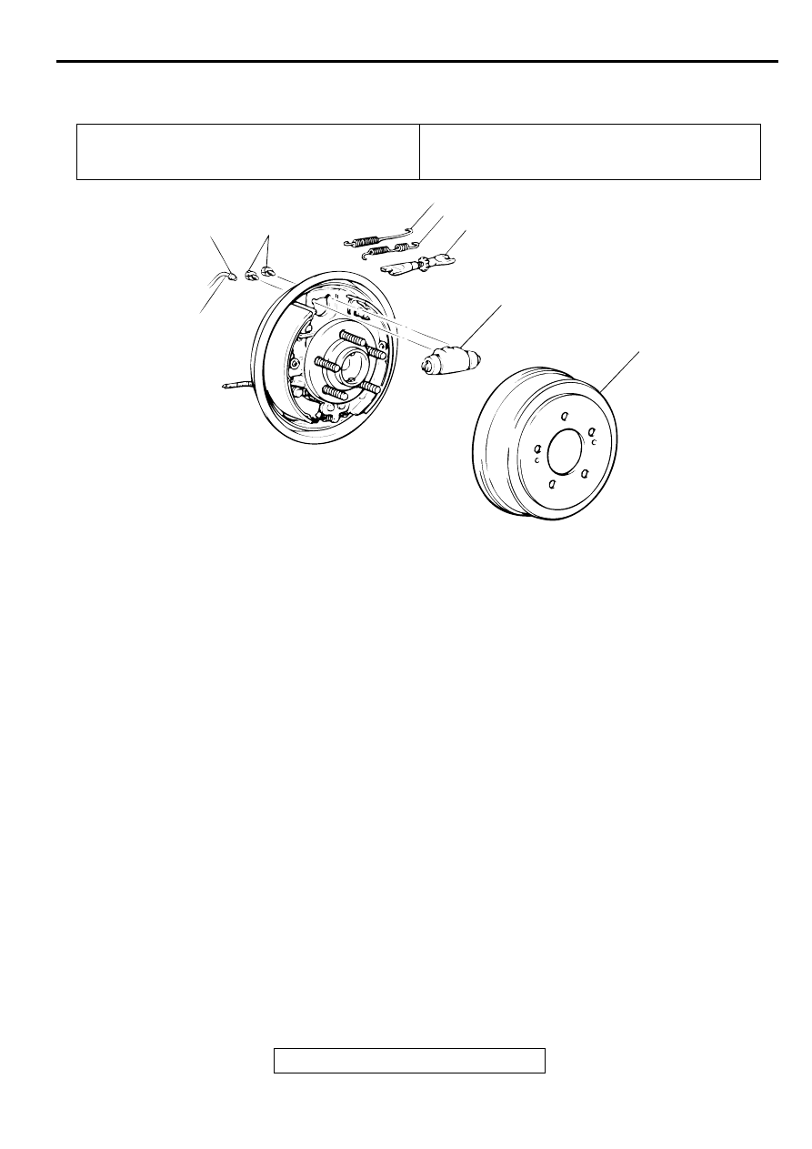
REAR DRUM BRAKE WHEEL CYLINDER

M1351009300043

REMOVAL AND INSTALLATION

Pre-removal Operation
Brake Fluid Draining

Post-installation Operation

Brake Fluid Filling

Brake Line Bleeding (Refer to 

P.35A-21

.)

AC000927 AC

15 N·m
11 ft-lb

10 N·m
89 in-lb

5

3

2

4

6

1

 REMOVAL STEPS

1. BRAKE DRUM
2. SHOE-TO-LEVER SPRING
3. SHOE-TO-SHOE SPRING
4. AUTO ADJUSTER ASSEMBLY

5. CONNECTION FOR THE BRAKE 

PIPE

6. WHEEL CYLINDER

 REMOVAL STEPS (Continued)

REAR DRUM BRAKE

TSB Revision

BASIC BRAKE SYSTEM

35A-52

WHEEL CYLINDER

M1351007700056

DISASSEMBLY AND ASSEMBLY

Required Special Tool:
MB990619: Installer

ASSEMBLY SERVICE POINT

>>A<< PISTON CUP/PISTON REASSEMBLY
1. Use alcohol or brake fluid DOT 3 or DOT 4 to clean the 

wheel cylinder and the piston.

AC000928

2

6

2

GREASE: REPAIR KIT GREASE

1

4

4

1

WHEEL CYLINDER REPAIR KIT

GREASE

6

7.9 N·m
71 in-lb

N

1

3

4

N

2

7

5

4

N

3

2

N

1

AC

BRAKE FLUID:  DOT 3 OR DOT 4

DISASSEMBLY STEPS

1. BOOTS
2. PISTON ASSEMBLY

>>A<<

3. PISTON

>>A<<

4. PISTON CUP

5. SPRING
6. BLEEDER SCREW
7. WHEEL CYLINDER BODY

DISASSEMBLY STEPS (Continued)

PROPORTIONING VALVE

TSB Revision

BASIC BRAKE SYSTEM

35A-53

2. Apply brake fluid DOT 3 or DOT 4 to the piston cups and 

special tool MB990619.

CAUTION

In order to keep the piston cup from becoming twisted or 
slanted, slide the piston cup down special tool MB990619 
slowly and carefully, without stopping.
3. Set the piston cup on special tool MB990619 with the lip of 

the cup facing up. Fit the cup onto special tool MB990619, 
and then slide it down the outside of special tool MB990619 
into the piston groove.

INSPECTION

M1351007800053

Check the piston and wheel cylinder walls for rust, pitting, or 
damage. If there is any abnormality, replace the entire wheel 
cylinder assembly.

PR O PO R TIO N IN G  VA LVE

REMOVAL AND INSTALLATION

M1351005700050

AC000929AB

MB990619

PISTON

LIP MUST FACE UPWARDS.

Pre-removal Operation
Brake Fluid Draining

Post-installation Operation

Brake Fluid Supplying

Brake Line Bleeding (Refer to 

P.35A-21

.)

SPECIFICATIONS

TSB Revision

BASIC BRAKE SYSTEM

35A-54

INSTALLATION SERVICE POINT

>>A<< BRAKE PIPE CONNECTION
Connect the pipes to the hydraulic unit as shown in the 
illustration.
1. Proportioning valve 

 Rear brake (LH)

2. Proportioning valve 

 Rear brake (RH)

3. Proportioning valve 

 Front brake (RH)

4. Proportioning valve 

 Front brake (LH)

5. Proportioning valve 

 Master cylinder (secondary)

6. Proportioning valve 

 Master cylinder (primary)

SPECIFIC ATIO NS

FASTENER TIGHTENING SPECIFICATIONS

M1351009600066

AC002054

FLARED BRAKE LINE NUTS

15 N·m
11 ft-lb

1

1

1

2

AC

REMOVAL STEPS

>>A<<

1. BRAKE PIPE
2. PROPORTIONING VALVE

AC002055

1

2

3

4

5

6

AB

ITEMS

SPECIFICATIONS

Brake line

Brake tube flare nut

15 N

m (11 ft-lb)

Brake pedal

Pedal support member mounting bolt

12 N

m (106 in-lb)

Pedal support member mounting nut

14 N

m (124 in-lb)


Content   ..  513  514  515  516   ..