Mitsubishi Galant. Manual - part 513


  Index      Mitsubishi     Mitsubishi Galant - service repair manual 2001 year


Search            


Content   ..  511  512  513  514   ..


Mitsubishi Galant. Manual - part 513


REAR DISC BRAKE ASSEMBLY

TSB Revision

BASIC BRAKE SYSTEM

35A-43

INSTALLATION SERVICE POINT

>>A<< REAR BRAKE ASSEMBLY INSTALLATION
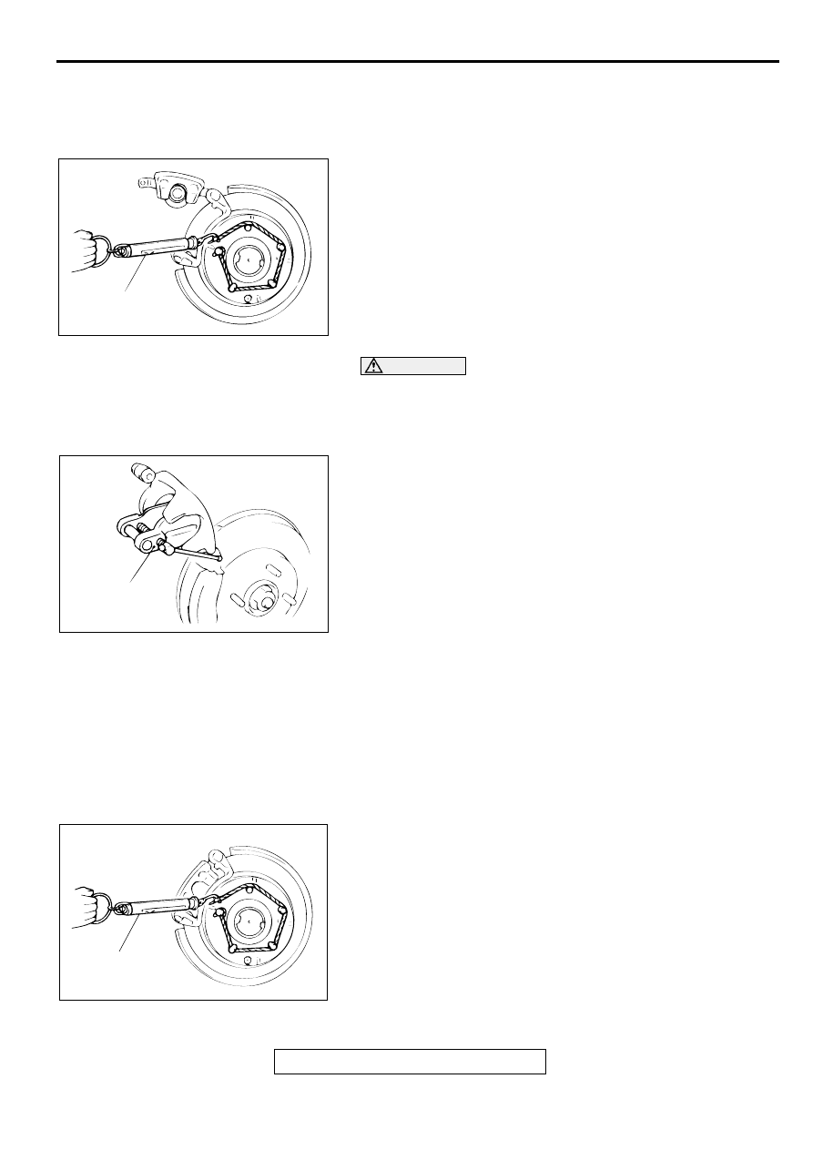
1. In order to measure brake drag torque after pad installation, 

measure hub torque with the pads removed.

2. Use a spring scale to measure hub torque in the direction 

shown. Record the value.

CAUTION

Do not let any oil, grease or other contamination get onto 
the friction surfaces of the pads and brake discs.
3. After re-installing the caliper support, install the pad clips 

and pads to the caliper support.

4. Clean the piston and insert it into the cylinder with special 

tool MB990520.

5. Be careful that the piston boot does not become caught, 

when lowering the caliper assembly and installing the guide 
pin.

6. Check brake drag force as follows:

(1) Start the engine and hold the brake pedal down for five 

seconds. [Pedal depression force: approximately 196 N 
(44 pound)]

(2) Stop the engine.
(3) Turn the brake disc forward ten times.
(4) Use a spring scale to measure the hub torque with pads 

installed in the same direction as earlier.

(5) Calculate the drag force of the disc brake [difference 

between hub torque with pads installed and hub torque 
with pads removed].

Standard value: 69 N (16 pound) or less

7. If the drag torque exceeds the standard value, disassemble 

and clean the piston. Check for corrosion or worn piston 
seal, and check the sliding condition of the lock pin and 
guide pin.

AC000917AB

SPRING
SCALE

AC000918

MB990520

AB

AC000919

SPRING
SCALE

AB

REAR DISC BRAKE ASSEMBLY

TSB Revision

BASIC BRAKE SYSTEM

35A-44

INSPECTION

M1351007100054

BRAKE DISC CHECK
Disc wear (Refer t

P.35A-24

.)

Disc run-out (Refer to 

P.35A-25

.)

Disc inside diameter (Refer to 

P.35A-28

.)

DISASSEMBLY AND ASSEMBLY

M1351007200040

AC000920

BRAKE CALIPER KIT

PAD SET

SHIM KIT

SEAL AND BOOT
REPAIR KIT

AD

17

CLIP KIT

16

13

14

12

17

5

N

3

2

11

1

7.9 N·m
71 in-lb

43 N·m
32 ft-lb

43 N·m
32 ft-lb

10

5

N

N

9

8

N

7

6

N

4

2

3 5

9 8

7

4

11

1

10

5

6

12

15

16

1314 16

14 13

9

3 5

5 7 6

GREASE

CALIPER ASSEMBLY DISASSEM-
BLY STEPS

>>A<<

1. GUIDE PIN

>>A<<

2. LOCK PIN
3. BUSHING
4. CALIPER SUPPORT, PAD, CLIP 

AND SHIM ASSEMBLY

5. BOOT
6. BOOT RING

<<A>>

7. PISTON BOOT

<<A>>

8. PISTON

<<B>>

9. PISTON SEAL
10. CALIPER BODY
11. BLEEDER SCREW

PAD ASSEMBLY DISASSEMBLY 
STEPS

>>A<<

1. GUIDE PIN

>>A<<

2. LOCK PIN

CALIPER ASSEMBLY DISASSEM-
BLY STEPS (Continued)

REAR DISC BRAKE ASSEMBLY

TSB Revision

BASIC BRAKE SYSTEM

35A-45

3. BUSHING
4. CALIPER SUPPORT, PAD, CLIP 

AND SHIM ASSEMBLY

12. PAD AND WEAR INDICATOR  

ASSEMBLY

13. INNER SHIM B
14. INNER SHIM A
15. PAD ASSEMBLY
16. OUTER SHIM
17. CLIP

PAD ASSEMBLY DISASSEMBLY 
STEPS (Continued)

REAR DISC BRAKE ASSEMBLY

TSB Revision

BASIC BRAKE SYSTEM

35A-46

LUBRICATION POINTS

DISASSEMBLY SERVICE POINTS

When disassembling the disc brakes, disassemble both sides 
(left and right) as a set.

AC000921

PISTON
SEAL

GREASE: REPAIR KIT GREASE

GREASE: REPAIR KIT GREASE

INNER SHIM A

INNER SHIM B

PAD AND WEAR
INDICATOR
ASSEMBLY

AC

GREASE: BRAKE GREASE J310, NLGI NO.1

THE PISTON SEAL INSIDE THE SEAL AND
BOOT KIT IS COATED WITH A SPECIAL
GREASE. DO NOT WIPE THIS GREASE OFF.

BRAKE FLUID:  DOT 3 OR DOT 4

!   CAUTION


Content   ..  511  512  513  514   ..