Mitsubishi Galant. Manual - part 511


  Index      Mitsubishi     Mitsubishi Galant - service repair manual 2001 year


Search            


Content   ..  509  510  511  512   ..


Mitsubishi Galant. Manual - part 511


FRONT DISC BRAKE ASSEMBLY

TSB Revision

BASIC BRAKE SYSTEM

35A-35

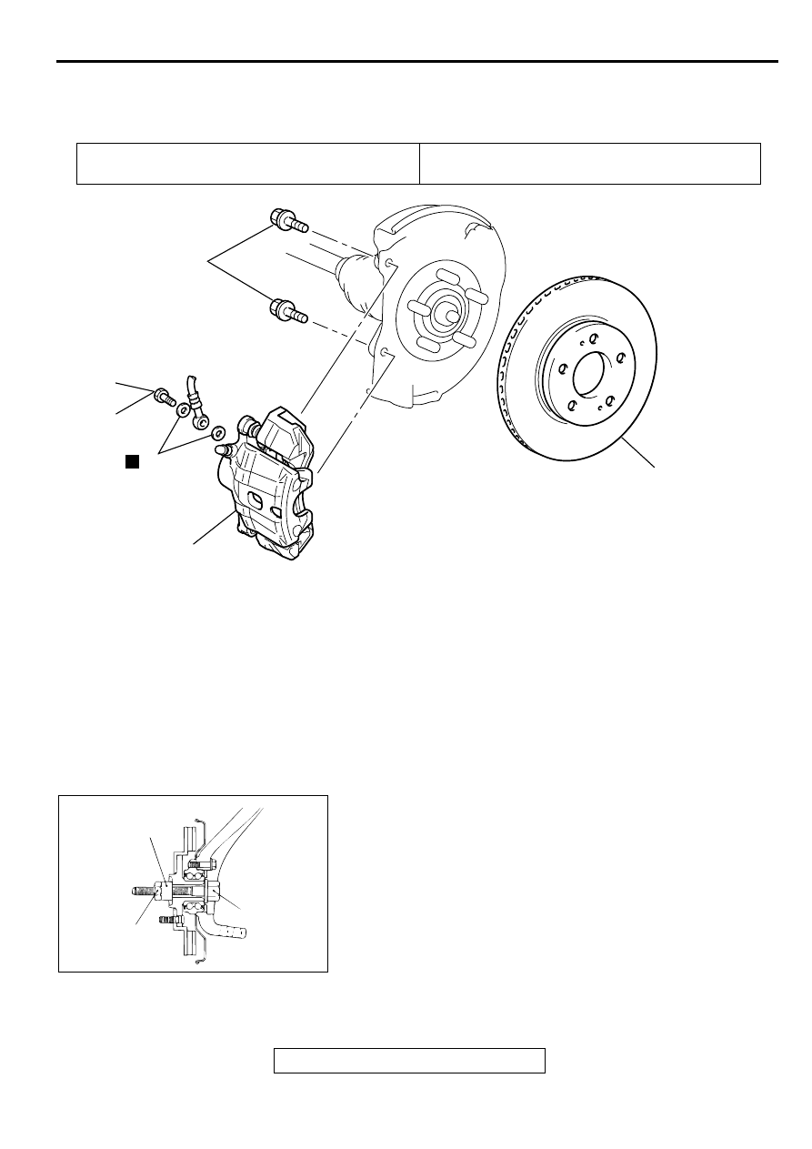
FR O N T DISC  B RA K E A SSEM BLY

REMOVAL AND INSTALLATION

M1351006000054

Required Special Tool:

MB990520: Disc Brake Piston Expander

MB990998: Front Hub Remover and Installer

INSTALLATION SERVICE POINT

>>A<< FRONT BRAKE ASSEMBLY INSTALLATION
1. In order to measure the brake drag torque, measure the hub 

torque with the pads removed by the following procedure.

(1) Remove the driveshaft. (Refer to GROUP 26, 

Driveshaft

P.26-11

.)

(2) Attach special tool MB990998 to the front hub assembly 

as shown in the illustration, and tighten it to the specified 
torque.

Tightening torque: 196 

−−−−

 255 N

⋅⋅⋅⋅

m (167 

−−−−

 188 ft-lb)

Pre-removal Operation
Brake Fluid Draining

Post-installation Operation
Brake Line Bleeding (Refer to 

P.35A-21

.)

AC003813

N

AB

90 - 110 N·m
66 - 81 ft-lb

2

1

3

29 N·m
21 ft-lb

4

REMOVAL STEPS

1. BRAKE HOSE CONNECTOR BOLT
2. GASKET

>>A<<

3. FRONT BRAKE ASSEMBLY
4. BRAKE DISC

AC000905 AB

MB990998

BOLT

TIGHTEN THE NUT
WITH THE BOLT
SECURED.

FRONT DISC BRAKE ASSEMBLY

TSB Revision

BASIC BRAKE SYSTEM

35A-36

(3) Use a spring scale to measure the hub torque in the 

forward direction. Record hub torque with pads removed.

CAUTION

Do not let any oil, grease or other contamination get onto 
the friction surfaces of the pads and brake discs.
2. After re-installing the caliper support to the knuckle, install 

the pad clips and the pads to the caliper support.

3. Clean the piston and insert into cylinder with special tool 

MB990520.

4. Be careful that the piston boot does not become caught, 

when lowering the caliper assembly and installing the guide 
pin.

5. Check the brake drag force as follows.

(1) Start the engine and hold the brake pedal down for 5 

seconds. [Pedal depression force: approximately 196 N 
(44 pound)]

(2) Stop the engine.
(3) Turn the brake disc forward 10 times.
(4) Use a spring scale to measure the hub torque with pads 

installed in the same direction as earlier.

(5) Calculate the drag force of the disc brake [difference 

between hub torque with pads installed and hub torque 
with pads removed].

Standard value: 69 N (16 pound) or less

6. If the brake drag force exceeds the standard value, 

disassemble and clean the piston. Check for corrosion or 
worn piston seal, and check the sliding condition of the lock 
pin and guide pin.

INSPECTION

M1351006100051

BRAKE DISC CHECK
Disc wear (Refer t

P.35A-24

.)

Disc run-out (Refer to 

P.35A-24

.)

AC000906

SPRING SCALE

AB

AC002027

MB990520

AB

AC000908

SPRING SCALE

AB

FRONT DISC BRAKE ASSEMBLY

TSB Revision

BASIC BRAKE SYSTEM

35A-37

DISASSEMBLY AND ASSEMBLY

M1351006200069

AC000910

BRAKE CALIPER KIT

PAD SET

SHIM KIT

SEAL AND BOOT
REPAIR KIT

AC

74 N·m
55 ft-lb

74 N·m
55 ft-lb

7.9 N·m
71 in-lb

CLIP KIT

18

18

18

15

17

16

13

14

12

9

N

18

5

N

3

2

11

1

10

5

N

8

N

7

N

6

4

11

2

3

10

5

9

8

7

6

4

1

5

12

15

13 141716

9 3 5

5 7

6

GREASE

<2.4L ENGINE>

13

14

17

16

CALIPER ASSEMBLY DISASSEM-
BLY STEPS

>>A<<

1. GUIDE PIN

>>A<<

2. LOCK PIN
3. BUSHING
4. CALIPER SUPPORT, PAD, CLIP 

AND SHIM ASSEMBLY

5. PIN BOOT
6. BOOT RING

<<A>>

7. PISTON BOOT

<<A>>

8. PISTON

<<B>>

9. PISTON SEAL

10. CALIPER BODY
11. BLEEDER SCREW

PAD ASSEMBLY DISASSEMBLY 
STEPS

>>A<<

1. GUIDE PIN

>>A<<

2. LOCK PIN
3. BUSHING
4. CALIPER SUPPORT, PAD, CLIP 

AND SHIM ASSEMBLY

12. PAD AND WEAR INDICATOR AS-

SEMBLY

CALIPER ASSEMBLY DISASSEM-
BLY STEPS (Continued)

FRONT DISC BRAKE ASSEMBLY

TSB Revision

BASIC BRAKE SYSTEM

35A-38

13. INNER SHIM B
14. INNER SHIM A
15. PAD ASSEMBLY
16. OUTER SHIM B
17. OUTER SHIM A
18. CLIP

PAD ASSEMBLY DISASSEMBLY 
STEPS (Continued)

AC003817

AC003817

BRAKE CALIPER KIT

PAD SET

SHIM SET

SEAL AND BOOT
REPAIR KIT

AB

38 N·m
28 ft-lb

38 N·m
28 ft-lb

.9 N·m
0 in-lb

CLIP SET

15

16

13

14

12

9

N

N

3

2

11

1

10

5

N

8

N

7

N

6

4

GREASE

<3.0L ENGINE>

6

16

15

14

9

3

2

11

1

10

5

8

7

6

4

1

6

13

12

13

16

16

10

8

7

6

4

6

1

CALIPER ASSEMBLY DISASSEM-
BLY STEPS

1. PIN BOLT

>>B<<

2. GUIDE PIN

>>B<<

3. LOCK PIN

>>B<<

4. BUSHING
5. CALIPER SUPPORT, PAD, CLIP 

AND SHIM ASSEMBLY

6. PIN BOOT

7. BOOT RING

<<A>>

8. PISTON BOOT

<<A>>

9 . PISTON

<<B>>

10. PISTON SEAL
11. CALIPER BODY

CALIPER ASSEMBLY DISASSEM-
BLY STEPS (Continued)


Content   ..  509  510  511  512   ..