Mitsubishi Galant. Manual - part 510


  Index      Mitsubishi     Mitsubishi Galant - service repair manual 2001 year


Search            


Content   ..  508  509  510  511   ..


Mitsubishi Galant. Manual - part 510


MASTER CYLINDER ASSEMBLY AND BRAKE BOOSTER

TSB Revision

BASIC BRAKE SYSTEM

35A-31

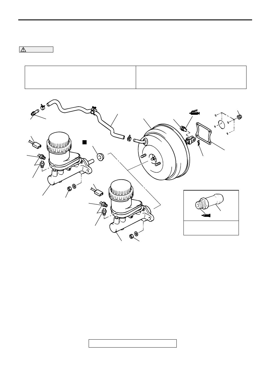
M A STER C YLIN DER  ASSEM B LY AN D  B R A K E B O O STER

REMOVAL AND INSTALLATION

M1351003700054

CAUTION

Do not remove the check valve from the vacuum hose. If the check valve is defective, replace it 
together with the vacuum hose.

Pre-removal Operation
Brake Fluid Draining

Post-installation Operation

Brake Fluid Supplying

Brake Line Bleeding (Refer to 

P.35A-21

.)

Brake Pedal Adjustment (Refer to 

P.35A-17

.)

AC003755

13 N·m
113 in-lb

5

4

2

1

1

15 N·m
11 ft-lb

3

10

8

N

6

9

14 N·m
124 in-lb

10 N·m
89 in-lb

5

SEALANT: 3M™ AAD PART
NO. 8661, 8663, 8672, 8678, 
8679 OR EQUIVALENT

AB

7

1

1

15 N·m
11 ft-lb

2

3

15 - 18 N·m
11 - 13 ft-lb

<VEHICLES WITH TCL>

<VEHICLES WITHOUT TCL>

REMOVAL STEPS

1. BRAKE TUBE CONNECTION
2. BRAKE FLUID LEVEL SENSOR 

CONNECTOR

3. MASTER CYLINDER ASSEMBLY

>>B<<

ADJUSTMENT OF CLEARANCE BE-
TWEEN BRAKE BOOSTER PUSH-
ROD AND PRIMARY PISTON

>>A<<

4. VACUUM HOSE (WITH BUILT-IN 

CHECK VALVE)

5. FITTING
6. SNAP PIN
7. CLEVIS PIN
8. BRAKE BOOSTER
9. SEALER
10. PLATE AND SEAL ASSEMBLY <VE-

HICLES WITH TCL>

REMOVAL STEPS (Continued)

MASTER CYLINDER ASSEMBLY AND BRAKE BOOSTER

TSB Revision

BASIC BRAKE SYSTEM

35A-32

INSTALLATION SERVICE POINTS

>>A<< VACUUM HOSE CONNECTION
1. Install the vacuum hose with the white-marked sections 

facing up.

2. Insert securely and completely until the vacuum hose at the 

engine side contacts the edge of the hexagonal part of the 
fitting, and then secure with the hose clamp.

>>B<< CLEARANCE ADJUSTMENT BETWEEN BRAKE 
BOOSTER PUSHROD AND PRIMARY PISTON
1. Using a hand vacuum pump, apply a negative pressure of -

66.7 kPa (19.6 inHg) to the brake booster.

2. Measure protruding length A at the pushrod.

Standard value (A): 10.28 

−−−−

 10.53 mm (0.404 

−−−−

 0.415 

inch)

3. If the protruding length is not within the standard value 

range, adjust by changing the pushrod length by turning the 
end of the pushrod.

AC000899

WHITE MARKS

FITTING

VACUUM HOSE

AB

AC000900AB

A

AC000901

MASTER CYLINDER ASSEMBLY AND BRAKE BOOSTER

TSB Revision

BASIC BRAKE SYSTEM

35A-33

MASTER CYLINDER

M1351004200052

DISASSEMBLY AND ASSEMBLY

CAUTION

Do not disassemble the primary piston and secondary piston assembly.

AC000902

2

3

1

4

6

7

5

11

10

N

9

N

8

N

10

9

8

MASTER CYLINDER KIT

11

10

9

BRAKE FLUID: DOT 3 OR DOT 4

AC

<VEHICLES WITHOUT TCL>

DISASSEMBLY STEPS

1. RESERVOIR CAP ASSEMBLY
2. RESERVOIR CAP
3. DIAPHRAGM
4. BRAKE FLUID LEVEL INDICATOR 

ASSEMBLY

5. SPRING PIN

6. RESERVOIR TANK
7. RESERVOIR SEAL

<<A>>

8. PISTON STOPPER RING
9. PRIMARY PISTON ASSEMBLY
10. SECONDARY PISTON ASSEMBLY
11. MASTER CYLINDER BODY

DISASSEMBLY STEPS (Continued)

MASTER CYLINDER ASSEMBLY AND BRAKE BOOSTER

TSB Revision

BASIC BRAKE SYSTEM

35A-34

DISASSEMBLY SERVICE POINT

<<A>> PISTON STOPPER RING DISASSEMBLY
Remove the piston stopper ring while depressing the piston.

INSPECTION

M1351004300059

Check the inner surface of master cylinder body for rust or 
pitting.

Check the primary and secondary pistons for rust, scoring, 
wear or damage.

Check the diaphragm for cracks and wear.

AC003756

2

3

1

4

6

7

5

12

11

N

10

N

8

N

11

10

9

MASTER CYLINDER KIT

12

11

10

BRAKE FLUID: DOT 3 OR DOT 4

AB

<VEHICLES WITH TCL>

9

8

DISASSEMBLY STEPS

1. RESERVOIR CAP ASSEMBLY
2. RESERVOIR CAP
3. DIAPHRAGM
4. BRAKE FLUID LEVEL INDICATOR 

ASSEMBLY

5. SPRING PIN
6. RESERVOIR TANK

7. RESERVOIR SEAL

<<A>>

8. PISTON STOPPER RING
9. PLATE
10. PRIMARY PISTON ASSEMBLY
11. SECONDARY PISTON ASSEMBLY
12. MASTER CYLINDER BODY

DISASSEMBLY STEPS (Continued)

AC000903


Content   ..  508  509  510  511   ..