Mitsubishi Galant. Manual - part 512
FRONT DISC BRAKE ASSEMBLY
TSB Revision
BASIC BRAKE SYSTEM
35A-39
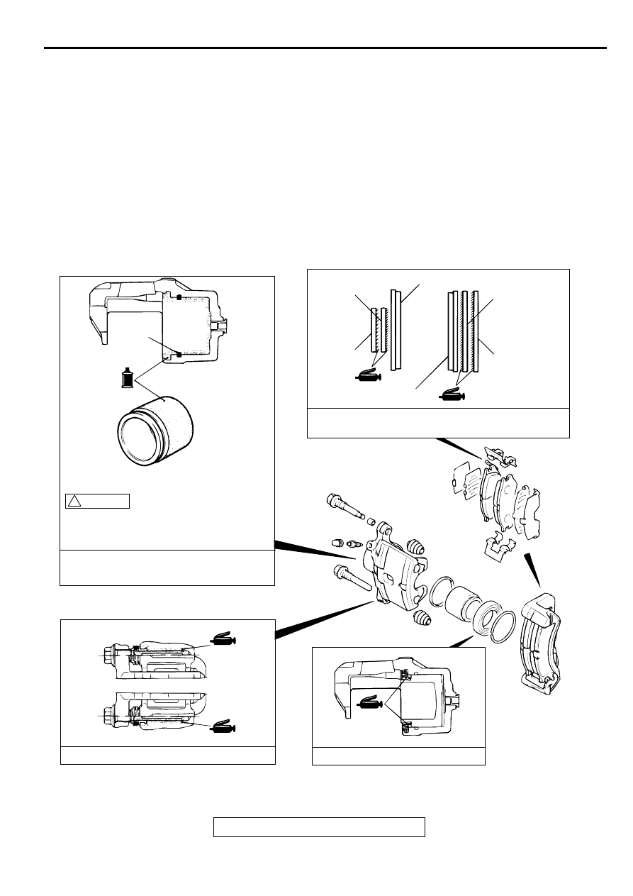
LUBRICATION POINTS
PAD ASSEMBLY DISASSEMBLY
STEPS
1. PIN BOLT
>>B<<
2. GUIDE PIN
>>B<<
3. LOCK PIN
>>B<<
4. BUSHING
5. CALIPER SUPPORT, PAD, CLIP
AND SHIM ASSEMBLY
12. PAD AND WEAR INDICATOR AS-
SEMBLY
13. PAD ASSEMBLY
14. INNER SHIM
15. OUTER SHIM
16. PAD CLIP
AC000911
PISTON
SEAL
INNER
SHIM A
INNER
SHIM B
OUTER
SHIM A
OUTER
SHIM B
PAD AND WEAR INDICATOR
ASSEMBLY
PAD ASSEMBLY
GREASE: BRAKE GREASE SAE J310, NLGI NO.1
THE PISTON SEAL INSIDE THE SEAL
AND BOOT KIT IS COATED WITH A
SPECIAL GREASE. DO NOT WIPE
THIS GREASE OFF.
BRAKE FLUID: DOT 3 OR DOT 4
GREASE: REPAIR KIT GREASE
GREASE: REPAIR KIT GREASE
AC
! CAUTION
<2.4L ENGINE>