Mitsubishi Galant. Manual - part 500
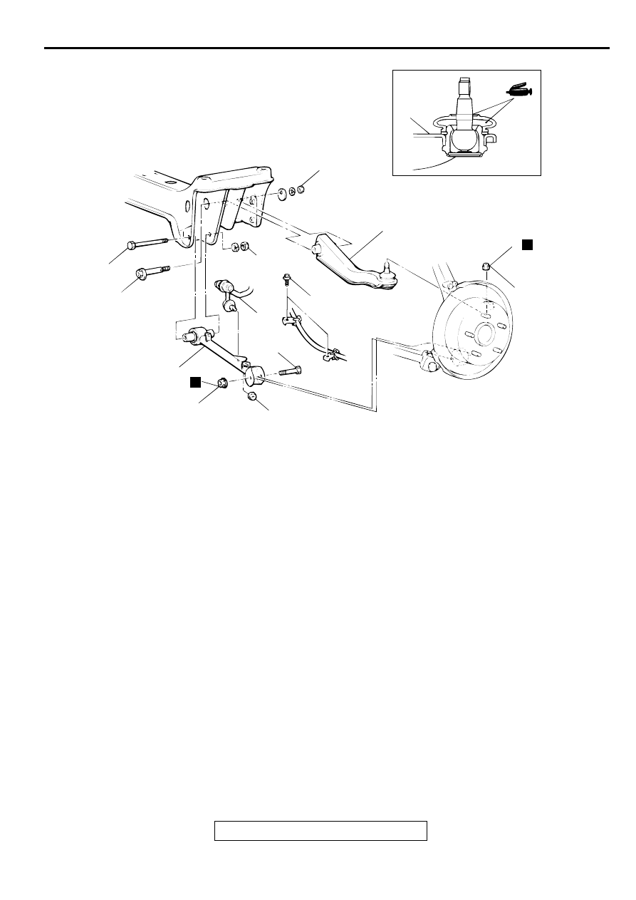
LOWER ARM AND TOE CONTROL ARM ASSEMBLY
TSB Revision
REAR SUSPENSION
34-13
Required Special Tools:
•
MB990326: Preload Socket
•
MB990635 or MB991113: Steering Linkage Puller
•
MB990800: Ball Joint Remover and Installer
AC001064
8
8
108 N·m*
80 ft-lb*
N
6
28 N·m
21 ft-lb
69 – 78 N·m*
51 – 58 ft-lb*
2
1
3
39 N·m
29 ft-lb
N
4
7
5
98 N·m*
72 ft-lb*
AC
LOWER ARM ASSEMBLY
REMOVAL STEPS
1.
STABILIZER LINK CONNECTION
2.
WHEEL SPEED SENSOR
MOUNTING BOLTS
3.
LOWER ARM ASSEMBLY AND
KNUCKLE CONNECTING BOLT
4.
LOWER ARM ASSEMBLY
MOUNTING BOLT
5.
LOWER ARM ASSEMBLY
TOE CONTROL ARM ASSEMBLY
REMOVAL STEPS
<<A>>
6.
TOE CONTROL ARM AND
KNUCKLE CONNECTION
<<B>>
7.
TOE CONTROL ARM ASSEMBLY
MOUNTING BOLT
8.
TOE CONTROL ARM ASSEMBLY