Mitsubishi Galant. Manual - part 499


  Index      Mitsubishi     Mitsubishi Galant - service repair manual 2001 year


Search            


Content   ..  497  498  499  500   ..


Mitsubishi Galant. Manual - part 499


UPPER ARM ASSEMBLY

TSB Revision

REAR SUSPENSION

34-9

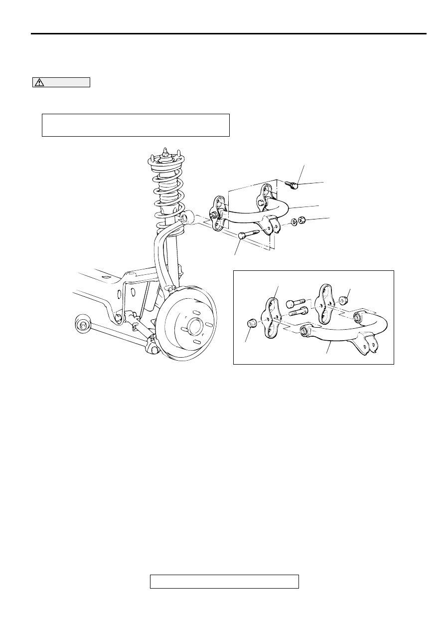
UPPER A RM  A SSEM B LY

REMOVAL AND INSTALLATION

M1341003600056

CAUTION


*

: Indicates parts which should be temporarily tightened, and then fully tightened with the vehicle on 

the ground in the unladen condition.

Post-installation Operation
Wheel Alignment Check and Adjustment (Refer to 

P.34-5

.)

AC001060

39 N·m
29 ft-lb

98 N·m*
72 ft-lb*

57 N·m
42 ft-lb

57 N·m
42 ft-lb

4

5

1

2

3

AC

REMOVAL STEPS

1.

UPPER ARM AND KNUCKLE 
CONNECTING BOLT

2.

UPPER ARM ASSEMBLY 
MOUNTING BOLTS

3.

UPPER ARM ASSEMBLY

>>A<<

4.

UPPER ARM BRACKET

5.

UPPER ARM

REMOVAL STEPS (Continued)

TRAILING ARM ASSEMBLY

TSB Revision

REAR SUSPENSION

34-10

INSTALLATION SERVICE POINT

>>A<< UPPER ARM BRACKET INSTALLATION
Install the upper arm bracket so that the dimension shown in 
the illustration is at the standard value.

Standard value (A): 37.2 

±±±±

 2 mm (1.46 

±±±±    

0.08 inches)

NOTE: Refer to distances B and C shown in the illustration to 
check the installation angle of the upper arm bracket.

INSPECTION

M1341003700053

Check the bushings for wear and deterioration.

Check the upper arm for bends or damage.

Check all bolts for condition and straightness.

TR AILING  A R M  A SSEM BLY

REMOVAL AND INSTALLATION

M1341002200022

CAUTION


*

: Indicates parts which should be temporarily tightened, and then fully tightened with the vehicle on 

the ground in the unladen condition.

AC001061AB

A

UPPER ARM

UPPER ARM BRACKET

AC001062

B: 220.1 mm (8.67 in)
C: 274.4 mm (10.80 in) 

B

C

B

C

AB

Post-installation Operation
Wheel Alignment Check and Adjustment (Refer to 

P.34-5

.)

TRAILING ARM ASSEMBLY

TSB Revision

REAR SUSPENSION

34-11

AC001063

137 – 157 N·m*
101 – 116 ft-lb*

118 – 137 N·m*
87 – 101 ft-lb*

4

5

5

4

3

2

6

1

AC

REMOVAL STEPS

1.

KNUCKLE AND TRAILING ARM 
ASSEMBLY CONNECTING BOLT

2.

GROMMET

3.

TRAILING ARM ASSEMBLY 
MOUNTING BOLT

>>A<<

4.

STOPPER A

>>A<<

5.

STOPPER B

6.

TRAILING ARM ASSEMBLY

REMOVAL STEPS (Continued)

LOWER ARM AND TOE CONTROL ARM ASSEMBLY

TSB Revision

REAR SUSPENSION

34-12

INSTALLATION SERVICE POINT

>>A<< STOPPER B/STOPPER A INSTALLATION
1. Install stopper B in the shown direction.

2. Install stopper A in the shown direction while checking that 

the notches on stopper A are engaged with the projections 
on the trailing arm bushing.

INSPECTION

M1341002300029

Check the bushings for wear and deterioration.

Check the trailing arm for bends or damage.

LO W ER AR M  AN D  TO E CO N TR O L A R M  ASSEM B LY

REMOVAL AND INSTALLATION

M1341004500052

CAUTION


*

: Indicates parts which should be temporarily tightened, and then fully tightened with the vehicle on 

the ground in the unladen condition.

AC001059

STOPPER A

STOPPER A

STOPPER B

STOPPER B

TRAILING ARM

TRAILING ARM

NOTCHES AND PROJECTIONS

AB

Post-installation Operation

Check the Dust Cover for Cracks or Damage by Pushing 
it with Your Finger. 

Wheel Alignment Check and Adjustment 
(Refer to 

P.34-5

.)


Content   ..  497  498  499  500   ..