Mitsubishi Galant. Manual - part 491


  Index      Mitsubishi     Mitsubishi Galant - service repair manual 2001 year


Search            


Content   ..  489  490  491  492   ..


Mitsubishi Galant. Manual - part 491


ENGINE ROLL STOPPER AND CENTERMEMBER

TSB Revision

POWER PLANT MOUNT

32-9

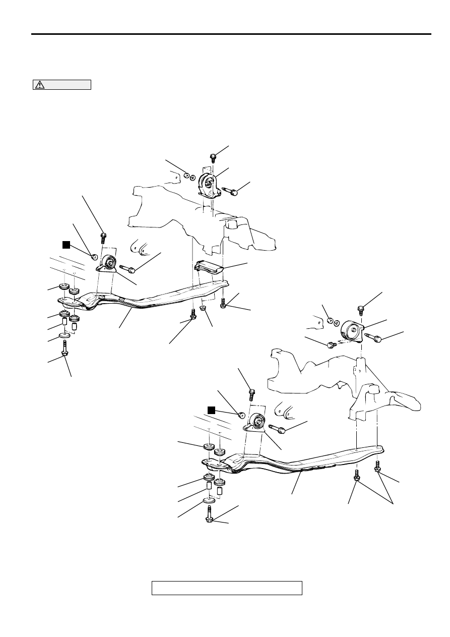
EN G INE R O LL STO PPER  A N D  C ENTER M EM BER

REMOVAL AND INSTALLATION

M1321002300049

CAUTION

Mounting locations marked by 

*

should be provisionally tightened, and then fully tightened after 

placing the vehicle horizontally and loading the full weight of the engine on the vehicle body.

AC005074

45 N·m
33 ft-lb

45 N·m
33 ft-lb

45 N·m*
33 ft-lb*

69 – 78 N·m
51 – 58 ft-lb

93 N·m
69 ft-lb

45 N·m
33 ft-lb

45 N·m*
33 ft-lb*

45 N·m
33 ft-lb

45 N·m
33 ft-lb

45 N·m*
33 ft-lb*

93 N·m
69 ft-lb

69 – 78 N·m
51 – 58 ft-lb

45 N·m*
33 ft-lb*

<3.0L ENGINE>

2.4L ENGINE>

1

2

2

2

4

5

6

7

8

3

10

11

11

10

1

5

4

8

7

6

3

2

2

2

AB

N

26 N·m
19 ft-lb

69 – 78 N·m
51 – 58 ft-lb

9

N

ENGINE ROLL STOPPER AND CENTERMEMBER

TSB Revision

POWER PLANT MOUNT

32-10

INSTALLATION SERVICE POINT

>>A<< FRONT ROLL STOPPER INSTALLATION
Install so that the hole in the front roll stopper is facing towards 
the front of the vehicle.

FRONT ROLL STOPPER, 
CENTERMEMBER REMOVAL 
STEPS

1.

TRANSAXLE AND FRONT ROLL 
STOPPER CONNECTING BOLT

2.

CENTERMEMBER MOUNTING 
BOLTS

3.

STOPPER

4.

CENTERMEMBER

>>A<<

5.

FRONT ROLL STOPPER

6.

COLLAR

7.

BUSHING (LOWER)

8.

BUSHING (UPPER)

9.

DYNAMIC DAMPER <2.4L 
ENGINE>

REAR ROLL STOPPER 
REMOVAL STEPS

10. TRANSAXLE AND REAR ROLL 

STOPPER CONNECTING BOLT

11. REAR ROLL STOPPER

FRONT ROLL STOPPER, 
CENTERMEMBER REMOVAL 
STEPS (Continued)

AC000304 AB

FRONT OF VEHICLE

HOLE

CROSSMEMBER

TSB Revision

POWER PLANT MOUNT

32-11

CR O SSM EM B ER

REMOVAL AND INSTALLATION

M1321003200078

CAUTION

*

: Indicates parts which should be temporarily tightened, and then fully tightened with the vehicle 

on the ground in the unladen condition.

For vehicles with SRS, before removal of steering gear box, refer to GROUP 52B, center the front 
wheels and remove the ignition key. Failure to do so may damage the SRS clock spring and render 
the SRS system inoperative, risking serious injury.

Pre-removal Operation

Power Steering Fluid Draining (Refer to GROUP 37A, On-
vehicle Service 

 Fluid Replacement 

P.37A-16

.)

Centermember Removal (Refer to 

P.32-9

.)

Front Exhaust Pipe Removal (Refer to GROUP 15, 
Exhaust pipe and Main Muffler

P.15-18

<2.4L 

Engine>

P.15-19

<3.0L Engine>.)

Stabilizer Bar Removal (Refer to GROUP 33A, Stabilizer 
Bar

P.33A-15

.)

Rear Roll Stopper Removal (Refer to 

P.32-9

.)

Post-installation Operation

Rear Roll Stopper Installation (Refer to 

P.32-9

.)

Stabilizer Bar Installation (Refer to GROUP 33A, 
Stabilizer Bar

P.33A-15

.)

Front Exhaust Pipe Installation (Refer to GROUP 15, 
Exhaust Pipe and Main Muffler

P.15-18

<2.4L 

Engine>

P.15-19

<3.0L Engine>..)

Centermember Installation (Refer to 

P.32-9

.)

Power Steering Fluid Supplying and Bleeding (Refer to 
GROUP 37A, On-vehicle Service 

 Fluid Replacement 

P.37A-16

.)

Steering Wheel Straight Ahead Position Checking.)

Wheel Alignment Check and Adjustment (Refer to 
GROUP 33A, On-vehicle Service 

 Front Wheel 

Alignment Check and Adjustment 

P.33A-5

.)

AC000305

6

7

8

9

10

4

11

5

4

2

1

3

98 – 118 N·m
72 – 87 ft-lb

98 – 118 N·m*
72 – 87 ft-lb*

88 N·m
65 ft-lb

86 N·m
63 ft-lb

98 – 118 N·m
72 – 87 ft-lb

AC

N

N

REMOVAL STEPS

1.

STAY <2.4L ENGINE>

2.

LOWER ARM AND 
CROSSMEMBER CONNECTION

3.

LOWER ARM CLAMP

POWER STEERING GEAR BOX 
(REFER TO GROUP 37A, POW-
ER STEERING GEAR BOX 

P.37A-

23

.)

REMOVAL STEPS (Continued)

CROSSMEMBER

TSB Revision

POWER PLANT MOUNT

32-12

Required Special Tools:

MB990828: Bushing Remover and Installer

MB991045: Bushing Remover and Installer

CROSSMEMBER BUSHING REPLACEMENT

M1321000900056

Crossmember Bushing A and B

1. Apply soapy water to the contact surface of the bushing 

when press-fitted the bushing.

2. The bushing should be press-fitted so that the inner pipe 

projection is at the standard length.

Standard values

••••

Bushing A: 9.0 

±±±±

 1.0 mm (0.35 

±±±±

 0.04 inch)

••••

Bushing B: 4.0 

±±±±

 1.0 mm (0.16 

±±±±

 0.04 inch)

Crossmember Bushing C

1. Use special tool MB990828 to drive out and press-fit the 

crossmember bushing C.

4.

CROSSMEMBER MOUNTING 
NUT

5.

LOWER PLATE

6.

CROSSMEMBER

7.

STOPPER A

8.

STOPPER B

9.

BUSHING C

REMOVAL STEPS (Continued)

10. BUSHING A
11. BUSHING B

REMOVAL STEPS (Continued)

AC000306

REMOVAL

PRESS-FITTING

BOLT

WASHER

NUT

BASE

BASE

NUT

WASHER

BOLT

MB991045

AB

AC000307AC

BUSHING A

BUSHING B

INNER PIPE

INNER PIPE

AC000309AB

REMOVAL

PRESS-FITTING

MB990828


Content   ..  489  490  491  492   ..