Mitsubishi Galant. Manual - part 246


  Index      Mitsubishi     Mitsubishi Galant - service repair manual 2001 year


Search            


Content   ..  244  245  246  247   ..


Mitsubishi Galant. Manual - part 246


MULTIPORT FUEL INJECTION(MFI) DIAGNOSIS

TSB Revision

MULTIPORT FUEL INJECTION (MFI) <3.0L>

13B-209

Intake air temperature is higher than -10

° 

C (14

° 

F).

Barometric pressure is higher than 76kPa (11 
psi).

Volume air flow sensor output frequency is 100 
Hz or less.

Judgment Criteria

Long-term fuel trim has continued to be lower 
than -12.5 for 5 seconds.

or

Short-term fuel trim has continued to be lower 
than -12.4 for 5 seconds.

Check Area

Under the closed loop air/fuel ratio control.

The left bank heated oxygen sensor (front) is 
active.

Judgment Criteria

Long-term fuel trim has continued to be lower 
than -12.5 for 5 seconds.

or

Short-term fuel trim has continued to be lower 
than -30.0 for 5 seconds.

TROUBLESHOOTING HINTS (The most likely 
causes for this code to be set are:)

Volume air flow sensor failed.

Injector (Number 2, 4, 6) failed.

Incorrect fuel pressure

Left bank heated oxygen sensor failed.

Engine coolant temperature sensor failed.

Intake air temperature sensor failed.

Barometric pressure sensor failed.

Exhaust leak.

Use of incorrect or contaminated fuel.

PCM failed.

DIAGNOSIS

Required Special Tools
MB991502: Scan Tool (MUT-II)

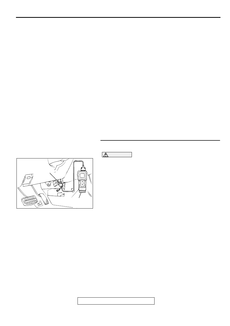
STEP 1. Using scan tool MB991502, check data list item 12: 
Volume Air Flow Sensor.

CAUTION

To prevent damage to scan tool MB991502, always turn the 
ignition switch to the "LOCK"(OFF) position before 
connecting or disconnecting scan tool MB991502.
(1) Connect scan tool MB991502 to the data link connector.
(2) Start the engine and run at idle.
(3) Set scan tool MB991502 to the data reading mode for item 

12, Volume Air Flow Sensor.

(4) Warm up the engine to normal operating temperature: 80

°


C to 96

°

 C (176

° 

F to 205

° 

F).

When idling, between 17 and 46 Hz (between 2.2 and 
5.7 g/s).

When 2,500 r/min, between 63 and 103 Hz (between 
9.0 and 14.7 g/s).

(5) Turn the ignition switch to the "LOCK"(OFF) position.

Q: Is the sensor operating properly?

YES : Go to Step 2.
NO :  Refer to, DTC P0101 

 Volume Air Flow Circuit 

Range/Performance Problem(

P.13B-25

), DTC P0102 

 Volume Air Flow Circuit Low Input(

P.13B-31

), DTC 

P0103 - Volume Air Flow Circuit High Input(

P.13B-

34

).

AC003081 AB

16 PIN

MB991502

MULTIPORT FUEL INJECTION(MFI) DIAGNOSIS

TSB Revision

MULTIPORT FUEL INJECTION (MFI) <3.0L>

13B-210

STEP 2. Using scan tool MB991502, check data list item 13: 
Intake Air Temperature Sensor.
(1) Turn the ignition switch to the "ON" position.
(2) Set scan tool MB991502 to the data reading mode for item 

13, Intake Air Temperature Sensor.

The intake air temperature and temperature shown with 
the scan tool should approximately match.

(3) Turn the ignition switch to the "LOCK"(OFF) position.

Q: Is the sensor operating properly?

YES : Go to Step 3.
NO :  Refer to, DTC P0111 

 Intake Air Temperature Circuit 

Range/Performance Problem(

P.13B-56

).

STEP 3. Using scan tool MB991502, check data list item 21: 
Engine Coolant Temperature Sensor.
(1) Turn the ignition switch to the "ON" position.
(2) Set scan tool MB991502 to the data reading mode for item 

21, Engine Coolant Temperature Sensor.

The engine coolant temperature and temperature 
shown with the scan tool should approximately match.

(3) Turn the ignition switch to the "LOCK"(OFF) position.

Q: Is the sensor operating properly?

YES : Go to Step 4.
NO :  Refer to, DTC P0115 

 Engine Coolant Temperature 

Circuit High Input(

P.13B-65

), DTC P0116 

 Engine 

Coolant Temperature Circuit Range/Performance 
Problem(

P.13B-73

), DTC P0117 

 Engine Coolant 

Temperature Circuit Low Input(

P.13B-78

).

STEP 4. Using scan tool MB991502, check data list item 25: 
Barometric Pressure Sensor.
(1) Turn the ignition switch to the "ON" position.
(2) Set scan tool MB991502 to the data reading mode for item 

25, Barometric Pressure Sensor.

When altitude is 0 m(0 foot), 101 kPa.

When altitude is 600 m(1,969 feet), 95 kPa.

When altitude is 1,200 m(3,937 feet), 88 kPa.

When altitude is 1,800 m(5,906 feet), 81 kPa.

(3) Turn the ignition switch to the "LOCK"(OFF) position.

Q: Is the sensor operating properly?

YES : Go to Step 5.
NO :  Refer to, DTC P0107 

 Barometric Pressure Circuit 

Low Input(

P.13B-40

), DTC P0108 

 Barometric 

Pressure Circuit High Input(

P.13B-49

).

AC003081 AB

16 PIN

MB991502

AC003081 AB

16 PIN

MB991502

AC003081 AB

16 PIN

MB991502

MULTIPORT FUEL INJECTION(MFI) DIAGNOSIS

TSB Revision

MULTIPORT FUEL INJECTION (MFI) <3.0L>

13B-211

STEP 5. Check the left bank injector.
(1) Disconnect the left bank injector connector B-17, B-21, B-

30.

(2) Measure the resistance between each injector side 

connector terminal 1 and 2.

Standard value: 13 

−−−−

 16 ohm [at 20

°°°°    

C (68

°°°°

 F)]

Q: Is the resistance standard value?

YES : Go to Step 6.
NO :  Replace the faulty injector. Then go to Step 8.

STEP 6. Check the fuel pressure.
Refer to, Fuel Pressure Test(

P.13B-522

).

Q: Is the fuel pressure normal?

YES : Go to Step 7.
NO :  Repair or replace it. Then go to Step 8.

STEP 7. Replace the left bank injector.
(1) Replace the left bank injector.
(2) Carry out a test drive with the drive cycle pattern. Refer to, 

Procedure 2 

 Fuel Trim Monitor(

P.13B-4

).

(3) Check the diagnostic trouble code (DTC).

Q: Is the DTC P0175 is output?

YES : Replace the PCM. Then go to Step 8.
NO :  The inspection is complete.

STEP 8. Test the OBD-II drive cycle.
(1) Carry out a test drive with the drive cycle pattern. Refer to, 

Procedure 2 

 Fuel Trim Monitor(

P.13B-4

).

(2) Check the diagnostic trouble code (DTC).

Q: Is the DTC P0175 is output?

YES : Retry the troubleshooting.
NO :  The inspection is complete.

AK000618 AD

CONNECTORS:B-17,B-21,B-30

B-30

B-17

B-21

AK000559

2

1

INJECTOR SIDE
CONNECTOR

AB

AK000618 AD

CONNECTORS:B-17,B-21,B-30

B-30

B-17

B-21

MULTIPORT FUEL INJECTION(MFI) DIAGNOSIS

TSB Revision

MULTIPORT FUEL INJECTION (MFI) <3.0L>

13B-212

DTC P0201: Injector Circuit Malfunction 

−−−−

 Cylinder 1, DTC P0203: Injector Circuit Malfunction 

−−−−


Cylinder 3, DTC P0205: Injector Circuit Malfunction 

−−−−

 Cylinder 5

AK000510

1 2
3

4

1 2
3

4

YELLO

W

-

BLUE

YELLO

W

-

BLUE

YELLO

W

-

BLA

CK

YELLO

W

-

BLA

CK

GREEN-

RED

GREEN-

RED

RED

RED

RED

RED

RED-

WHITE

RED-

WHITE

RED-

WHITE

BATTERY

MFI
RELAY

A-21X

INJECTOR
NO.1

INJECTOR
NO.3

INJECTOR
NO.5

1

1

1

1

2

2

2

2

3

4

1

24

10

2

3

4

1

POWERTRAIN CONTROL
MODULE(PCM)

     B-26
MU802605

      C-39
(MU803784)

2

3 4

5 6

7 8

9

11 12 13 14 15 16 17 18 19 20

30

21 22 23

24 25

26 27 28 29

3132 33

34 35

1

10

B-22

2

1

B-19

2

1

B-25

2

1


Content   ..  244  245  246  247   ..