Mitsubishi Galant. Manual - part 245
 

  Index      Mitsubishi     Mitsubishi Galant - service repair manual 2001 year


Search            


Content   ..  243  244  245  246   ..


Mitsubishi Galant. Manual - part 245


MULTIPORT FUEL INJECTION(MFI) DIAGNOSIS

TSB Revision

MULTIPORT FUEL INJECTION (MFI) <3.0L>

13B-205

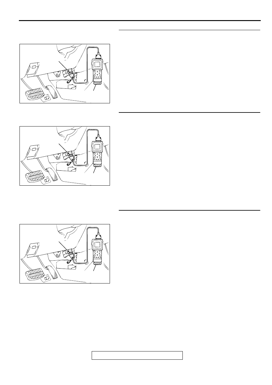
STEP 4. Using scan tool MB991502, check data list item 13: 
Intake Air Temperature Sensor.
(1) Turn the ignition switch to the "ON" position.
(2) Set scan tool MB991502 to the data reading mode for item 

13, Intake Air Temperature Sensor.

•

The intake air temperature and temperature shown with 
the scan tool should approximately match.

(3) Turn the ignition switch to the "LOCK"(OFF) position.

Q: Is the sensor operating properly?

YES : Go to Step 5.
NO :  Refer to, DTC P0111 

−

 Intake Air Temperature Circuit 

Range/Performance Problem(

P.13B-56

).

STEP 5. Using scan tool MB991502, check data list item 21: 
Engine Coolant Temperature Sensor.
(1) Turn the ignition switch to the "ON" position.
(2) Set scan tool MB991502 to the data reading mode for item 

21, Engine Coolant Temperature Sensor.

•

The engine coolant temperature and temperature 
shown with the scan tool should approximately match.

(3) Turn the ignition switch to the "LOCK"(OFF) position.

Q: Is the sensor operating properly?

YES : Go to Step 6.
NO :  Refer to, DTC P0115 

−

 Engine Coolant Temperature 

Circuit High Input(

P.13B-65

), DTC P0116 

−

 Engine 

Coolant Temperature Circuit Range/Performance 
Problem(

P.13B-73

), DTC P0117 

−

 Engine Coolant 

Temperature Circuit Low Input(

P.13B-78

).

STEP 6. Using scan tool MB991502, check data list item 25: 
Barometric Pressure Sensor.
(1) Turn the ignition switch to the "ON" position.
(2) Set scan tool MB991502 to the data reading mode for item 

25, Barometric Pressure Sensor.

•

When altitude is 0 m(0 foot), 101 kPa.

•

When altitude is 600 m(1,969 feet), 95 kPa.

•

When altitude is 1,200 m(3,937 feet), 88 kPa.

•

When altitude is 1,800 m(5,906 feet), 81 kPa.

(3) Turn the ignition switch to the "LOCK"(OFF) position.

Q: Is the sensor operating properly?

YES : Go to Step 7.
NO :  Refer to, DTC P0107 

−

 Barometric Pressure Circuit 

Low Input(

P.13B-40

), DTC P0108 

−

 Barometric 

Pressure Circuit High Input(

P.13B-49

).

AC003081 AB

16 PIN

MB991502

AC003081 AB

16 PIN

MB991502

AC003081 AB

16 PIN

MB991502

MULTIPORT FUEL INJECTION(MFI) DIAGNOSIS

TSB Revision

MULTIPORT FUEL INJECTION (MFI) <3.0L>

13B-206

STEP 7. Check connector B-17, B-21, B-30 at left bank 
injector for damage.
Q: Is the connector in good condition?

YES : Go to Step 8.
NO :  Repair or replace it. Refer to GROUP 00E, Harness 

Connector Inspection (

P.00E-2

). Then go to Step 14.

STEP 8. Check the left bank injector.
(1) Disconnect the left bank injector connector B-17, B-21, B-

30.

(2) Measure the resistance between each injector side 

connector terminal 1 and 2.

   Standard value: 13 

−−−−

 16 ohm [at 20

°°°°    

C (68

°°°°

 F)]

Q: Is the resistance standard value?

YES : Go to Step 9.
NO :  Replace the faulty injector. Then go to Step 14.

STEP 9. Check connector C-39 at PCM for damage.
Q: Is the connector in good condition?

YES : Go to Step 10.
NO :  Repair or replace it. Refer to GROUP 00E, Harness 

Connector Inspection (

P.00E-2

). Then go to Step 14.

AK000618 AD

CONNECTORS:B-17,B-21,B-30

B-30

B-17

B-21

AK000618 AD

CONNECTORS:B-17,B-21,B-30

B-30

B-17

B-21

AK000559

2

1

INJECTOR SIDE
CONNECTOR

AB

AK000280

CONNECTOR : C-39

PCM

AW

MULTIPORT FUEL INJECTION(MFI) DIAGNOSIS

TSB Revision

MULTIPORT FUEL INJECTION (MFI) <3.0L>

13B-207

STEP 10. Check for harness damage between left bank 
injector connector and PCM connector.

a. Check the harness wire between injector connector B-21 

terminal 2 and PCM connector C-39 terminal 9 when 
checking No.2 cylinder injector.

b. Check the harness wire between injector connector B-17 

terminal 2 and PCM connector C-39 terminal 2 when 
checking No.4 cylinder injector.

c. Check the harness wire between injector connector B-30 

terminal and 2 PCM connector C-39 terminal 25 when 
checking No.6 cylinder injector.

Q: Is the harness wire in good condition?

YES : Go to Step 11.
NO :  Repair it. Then go to Step 14.

STEP 11. Check the fuel pressure.
Refer to, Fuel Pressure Test(

P.13B-522

).

Q: Is the fuel pressure normal?

YES : Go to Step 12.
NO :  Repair or replace it. Then go to Step 14.

STEP 12. Check for entry of foreign matter (water, 
kerosene, etc.) into fuel.

Q: Are there any abnormalities?

YES : Go to Step 13.
NO :  Replace the fuel. Then go to Step 14.

STEP 13. Replace the left bank injector.
(1) Replace the left bank injector.
(2) Carry out a test drive with the drive cycle pattern. Refer to, 

Procedure 2 

−

 Fuel Trim Monitor(

P.13B-4

).

(3) Check the diagnostic trouble code (DTC).

Q: Is the DTC P0174 is output?

YES : Replace the PCM. Then go to Step 14.
NO :  The inspection is complete.

AK000618 AD

CONNECTORS:B-17,B-21,B-30

B-30

B-17

B-21

AK000280

CONNECTOR : C-39

PCM

AW

AK000618 AD

CONNECTORS:B-17,B-21,B-30

B-30

B-17

B-21

MULTIPORT FUEL INJECTION(MFI) DIAGNOSIS

TSB Revision

MULTIPORT FUEL INJECTION (MFI) <3.0L>

13B-208

STEP 14. Test the OBD-II drive cycle.
(1) Carry out a test drive with the drive cycle pattern. Refer to, 

Procedure 2 

−

 Fuel Trim Monitor(

P.13B-4

).

(2) Check the diagnostic trouble code (DTC).

Q: Is the DTC P0174 is output?

YES : Retry the troubleshooting.
NO :  The inspection is complete.

DTC P0175: System too Rich (bank 2)

System too Rich (bank 2) Circuit

•

Refer to, DTC P0202,P0204,P0206 

−

 Injector 

Circuit (

P.13B-220

).

CIRCUIT OPERATION

•

Refer to, DTC P0202,P0204,P0206 

−

 Injector 

Circuit (

P.13B-220

).

TECHNICAL DESCRIPTION

•

If a malfunction occurs in the fuel system, the fuel 
trim value becomes too small.

•

The PCM checks whether the fuel trim value is 
within a specified range.

DTC SET CONDITIONS

Check Area

•

Engine coolant temperature is lower than 
approximately 100

°

 C (212

°

 F) when the engine 

is started.

•

Intake air temperature is lower than 60

°

 C (140

°


F) when the engine is started.

•

Under the closed loop air/fuel ratio control.

•

Intake air temperature is higher than -10

° 

C (14

° 

F).

•

Barometric pressure is higher than 76kPa (11 
psi).

•

Volume air flow sensor output frequency is 100 
Hz or more.

Judgment Criteria

•

Long-term fuel trim has continued to be lower 
than -12.5 for 5 seconds.

or

•

Short-term fuel trim has continued to be lower 
than -7.4 for 5 seconds.

Check Area

•

Engine coolant temperature is lower than 
approximately 100

°

 C (212

°

 F) when the engine 

is started.

•

Intake air temperature is lower than 60

°

 C (140

°


F) when the engine is started.

•

Under the closed loop air/fuel ratio control.

•

Intake air temperature is higher than -10

° 

C (14

° 

F).

•

Barometric pressure is higher than 76kPa (11 
psi).

•

Volume air flow sensor output frequency is 100 
Hz or less.

Judgment Criteria

•

Long-term fuel trim has continued to be lower 
than -12.5 for 5 seconds.

or

•

Short-term fuel trim has continued to be lower 
than -12.4 for 5 seconds.

Check Area

•

Engine coolant temperature is higher than 
approximately 100

°

 C (212

°

 F) when the engine 

is started.

•

Intake air temperature is higher than 60

°

 C (140

°


F) when the engine is started.

•

Under the closed loop air/fuel ratio control.

•

Intake air temperature is higher than -10

° 

C (14

° 

F).

•

Barometric pressure is higher than 76kPa (11 
psi).

•

Volume air flow sensor output frequency is 100 
Hz or more.

Judgment Criteria

•

Long-term fuel trim has continued to be lower 
than -12.5 for 5 seconds.

or

•

Short-term fuel trim has continued to be lower 
than -7.4 for 5 seconds.

Check Area

•

Engine coolant temperature is higher than 
approximately 100

°

 C (212

°

 F) when the engine 

is started.

•

Intake air temperature is higher than 60

°

 C (140

°


F) when the engine is started.

•

Under the closed loop air/fuel ratio control.


Content   ..  243  244  245  246   ..