Mitsubishi Galant. Manual - part 243


  Index      Mitsubishi     Mitsubishi Galant - service repair manual 2001 year


Search            


Content   ..  241  242  243  244   ..


Mitsubishi Galant. Manual - part 243


MULTIPORT FUEL INJECTION(MFI) DIAGNOSIS

TSB Revision

MULTIPORT FUEL INJECTION (MFI) <3.0L>

13B-197

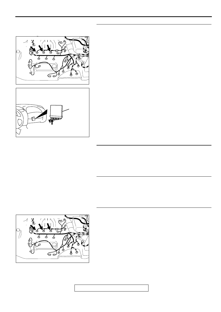
STEP 12. Check for harness damage between right bank 
injector connector and PCM connector.

a. Check the harness wire between injector connector B-22 

terminal 2 and PCM connector C-39 terminal 1 when 
checking No.1 cylinder.

b. Check the harness wire between injector connector B-19 

terminal 2 and PCM connector C-39 terminal 24 when 
checking No.3 cylinder.

c. Check the harness wire between injector connector B-25 

terminal 2 and PCM connector C-39 terminal 10 when 
checking No.5 cylinder.

Q: Is the harness wire in good condition?

YES : Go to Step 13.
NO :  Repair it. Then go to Step 16.

STEP 13. Check the fuel pressure.
Refer to, Fuel Pressure Test(

P.13B-522

).

Q: Is the fuel pressure normal?

YES : Go to Step 14.
NO :  Repair or replace it. Then go to Step 16.

STEP 14. Check for entry of foreign matter (water, 
kerosene, etc.) into fuel.

Q: Are there any abnormalities?

YES : Go to Step 15.
NO :  Replace the fuel. Then go to Step 16.

STEP 15. Replace the right bank injector.
(1) Replace the right bank injector.
(2) Carry out a test drive with the drive cycle pattern. Refer to, 

Procedure 2 

 Fuel Trim Monitor(

P.13B-4

).

(3) Check the diagnostic trouble code (DTC).

Q: Is the DTC P0171 is output?

YES : Replace the PCM. Then go to Step 16.
NO :  The inspection is complete.

AK000618AC

CONNECTORS:B-19,B-22,B-25

B-25

B-19

B-22

AK000280

CONNECTOR : C-39

PCM

AW

AK000618AC

CONNECTORS:B-19,B-22,B-25

B-25

B-19

B-22

MULTIPORT FUEL INJECTION(MFI) DIAGNOSIS

TSB Revision

MULTIPORT FUEL INJECTION (MFI) <3.0L>

13B-198

STEP 16. Test the OBD-II drive cycle.
(1) Carry out a test drive with the drive cycle pattern. Refer to, 

Procedure 2 

 Fuel Trim Monitor(

P.13B-4

).

(2) Check the diagnostic trouble code (DTC).

Q: Is the DTC P0171 is output?

YES : Retry the troubleshooting.
NO :  The inspection is complete.

DTC P0172: System too Rich (bank 1)

System too Rich (bank 1) Circuit

Refer to, DTC P0201,P0203,P0205 

 Injector 

Circuit (

P.13B-212

).

CIRCUIT OPERATION

Refer to, DTC P0201,P0203,P0205 

 Injector 

Circuit (

P.13B-212

).

TECHNICAL DESCRIPTION

If a malfunction occurs in the fuel system, the fuel 
trim value becomes too small.

The PCM checks whether the fuel trim value is 
within a specified range.

DTC SET CONDITIONS

Check Area

Engine coolant temperature is lower than 
approximately 100

°

 C (212

°

 F) when the engine 

is started.

Intake air temperature is lower than 60

°

 C (140

°


F) when the engine is started.

Under the closed loop air/fuel ratio control.

Intake air temperature is higher than -10

° 

C (14

° 

F).

Barometric pressure is higher than 76kPa (11 
psi).

Volume air flow sensor output frequency is 100 
Hz or more.

Judgment Criteria

Long-term fuel trim has continued to be lower 
than -12.5 for 5 seconds.

or

Short-term fuel trim has continued to be lower 
than -7.4 for 5 seconds.

Check Area

Engine coolant temperature is lower than 
approximately 100

°

 C (212

°

 F) when the engine 

is started.

Intake air temperature is lower than 60

°

 C (140

°


F) when the engine is started.

Under the closed loop air/fuel ratio control.

Intake air temperature is higher than -10

° 

C (14

° 

F).

Barometric pressure is higher than 76kPa (11 
psi).

Volume air flow sensor output frequency is 100 
Hz or less.

Judgment Criteria

Long-term fuel trim has continued to be lower 
than -12.5 for 5 seconds.

or

Short-term fuel trim has continued to be lower 
than -12.4 for 5 seconds.

Check Area

Engine coolant temperature is higher than 
approximately 100

°

 C (212

°

 F) when the engine 

is started.

Intake air temperature is higher than 60

°

 C (140

°


F) when the engine is started.

Under the closed loop air/fuel ratio control.

Intake air temperature is higher than -10

° 

C (14

° 

F).

Barometric pressure is higher than 76kPa (11 
psi).

Volume air flow sensor output frequency is 100 
Hz or more.

Judgment Criteria

Long-term fuel trim has continued to be lower 
than -12.5 for 5 seconds.

or

Short-term fuel trim has continued to be lower 
than -7.4 for 5 seconds.

Check Area

Engine coolant temperature is higher than 
approximately 100

°

 C (212

°

 F) when the engine 

is started.

Intake air temperature is higher than 60

°

 C (140

°


F) when the engine is started.

Under the closed loop air/fuel ratio control.

MULTIPORT FUEL INJECTION(MFI) DIAGNOSIS

TSB Revision

MULTIPORT FUEL INJECTION (MFI) <3.0L>

13B-199

Intake air temperature is higher than -10

° 

C (14

° 

F).

Barometric pressure is higher than 76kPa (11 
psi).

Volume air flow sensor output frequency is 100 
Hz or less.

Judgment Criteria

Long-term fuel trim has continued to be lower 
than -12.5 for 5 seconds.

or

Short-term fuel trim has continued to be lower 
than -12.4 for 5 seconds.

Check Area

Under the closed loop air/fuel ratio control.

The right bank heated oxygen sensor (front) is 
active.

Judgment Criteria

Long-term fuel trim has continued to be lower 
than -12.5 for 5 seconds.

or

Short-term fuel trim has continued to be lower 
than -30.0 for 5 seconds.

TROUBLESHOOTING HINTS (The most likely 
causes for this code to be set are:)

Volume air flow sensor failed.

Injector (Number 1, 3, 5) failed.

Incorrect fuel pressure

Right bank heated oxygen sensor failed.

Engine coolant temperature sensor failed.

Intake air temperature sensor failed.

Barometric pressure sensor failed.

Exhaust leak.

Use of incorrect or contaminated fuel.

PCM failed.

DIAGNOSIS

Required Special Tools
MB991502: Scan Tool (MUT-II)

STEP 1. Using scan tool MB991502, check data list item 12: 
Volume Air Flow Sensor.

CAUTION

To prevent damage to scan tool MB991502, always turn the 
ignition switch to the "LOCK"(OFF) position before 
connecting or disconnecting scan tool MB991502.
(1) Connect scan tool MB991502 to the data link connector.
(2) Start the engine and run at idle.
(3) Set scan tool MB991502 to the data reading mode for item 

12, Volume Air Flow Sensor.

(4) Warm up the engine to normal operating temperature: 80

°


C to 96

°

 C(176

° 

F to 205F

°

 ).

When idling, between 17 and 46 Hz (between 2.2 and 
5.7 g/s).

When 2,500 r/min, between 63 and 103 Hz (between 
9.0 and 14.7 g/s).

(5) Turn the ignition switch to the "LOCK"(OFF) position.

Q: Is the sensor operating properly?

YES : Go to Step 2.
NO :  Refer to, DTC P0101 

 Volume Air Flow Circuit 

Range/Performance Problem(

P.13B-25

), DTC P0102 

 Volume Air Flow Circuit Low Input(

P.13B-31

), DTC 

P0103 - Volume Air Flow Circuit High Input(

P.13B-

34

).

AC003081 AB

16 PIN

MB991502

MULTIPORT FUEL INJECTION(MFI) DIAGNOSIS

TSB Revision

MULTIPORT FUEL INJECTION (MFI) <3.0L>

13B-200

STEP 2. Using scan tool MB991502, check data list item 13: 
Intake Air Temperature Sensor.
(1) Turn the ignition switch to the "ON" position.
(2) Set scan tool MB991502 to the data reading mode for item 

13, Intake Air Temperature Sensor.

The intake air temperature and temperature shown with 
the scan tool should approximately match.

(3) Turn the ignition switch to the "LOCK"(OFF) position.

Q: Is the sensor operating properly?

YES : Go to Step 3.
NO :  Refer to, DTC P0111 

 Intake Air Temperature Circuit 

Range/Performance Problem(

P.13B-56

).

STEP 3. Using scan tool MB991502, check data list item 21: 
Engine Coolant Temperature Sensor.
(1) Turn the ignition switch to the "ON" position.
(2) Set scan tool MB991502 to the data reading mode for item 

21, Engine Coolant Temperature Sensor.

The engine coolant temperature and temperature 
shown with the scan tool should approximately match.

(3) Turn the ignition switch to the "LOCK"(OFF) position.

Q: Is the sensor operating properly?

YES : Go to Step 4.
NO :  Refer to, DTC P0115 

 Engine Coolant Temperature 

Circuit High Input(

P.13B-65

), DTC P0116 

 Engine 

Coolant Temperature Circuit Range/Performance 
Problem(

P.13B-73

), DTC P0117 

 Engine Coolant 

Temperature Circuit Low Input(

P.13B-78

).

STEP 4. Using scan tool MB991502, check data list item 25: 
Barometric Pressure Sensor.
(1) Turn the ignition switch to the "ON" position.
(2) Set scan tool MB991502 to the data reading mode for item 

25, Barometric Pressure Sensor.

When altitude is 0 m(0 foot), 101 kPa.

When altitude is 600 m(1,969 feet), 95 kPa.

When altitude is 1,200 m(3,937 feet), 88 kPa.

When altitude is 1,800 m(5,906 feet), 81 kPa.

(3) Turn the ignition switch to the "LOCK"(OFF) position.

Q: Is the sensor operating properly?

YES : Go to Step 5.
NO :  Refer to, DTC P0107 

 Barometric Pressure Circuit 

Low Input(

P.13B-40

), DTC P0108 

 Barometric 

Pressure Circuit High Input(

P.13B-49

).

AC003081 AB

16 PIN

MB991502

AC003081 AB

16 PIN

MB991502

AC003081 AB

16 PIN

MB991502


Content   ..  241  242  243  244   ..