Mitsubishi Galant. Manual - part 241


  Index      Mitsubishi     Mitsubishi Galant - service repair manual 2001 year


Search            


Content   ..  239  240  241  242   ..


Mitsubishi Galant. Manual - part 241


MULTIPORT FUEL INJECTION(MFI) DIAGNOSIS

TSB Revision

MULTIPORT FUEL INJECTION (MFI) <3.0L>

13B-189

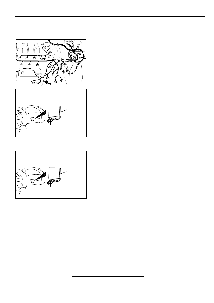
STEP 7. Check for open circuit or short circuit to ground 
between left bank heated oxygen sensor (rear) connector 
B-29 terminal 3 and PCM connector C-39 terminal 26.
Q: Is the harness wire in good condition?

YES : Replace the PCM. Then go to Step 12.
NO :  Repair it. Then go to Step 12.

STEP 8. Check connector C-39 at PCM for damage.
Q: Is the connector in good condition?

YES : Go to Step 9.
NO :  Repair or replace it. Refer to GROUP 00E, Harness 

Connector Inspection (

P.00E-2

). Then go to Step 12.

AK000619 AC

CONNECTOR:B-29

AK000280

CONNECTOR : C-39

PCM

AW

AK000280

CONNECTOR : C-39

PCM

AW

MULTIPORT FUEL INJECTION(MFI) DIAGNOSIS

TSB Revision

MULTIPORT FUEL INJECTION (MFI) <3.0L>

13B-190

STEP 9. Check for harness damage between MFI relay 
connector A-21X terminal 1 and left bank heated oxygen 
sensor (rear) connector B-29 terminal 1.
Q: Is the harness wire in good condition?

YES : Go to Step 10.
NO :  Repair it. Then go to Step 12.

STEP 10. Check for harness damage between left bank 
heated oxygen sensor (rear) connector B-29 terminal 3 and 
PCM connector C-39 terminal 26.
Q: Is the harness wire in good condition?

YES : Go to Step 11.
NO :  Repair it. Then go to Step 12.

AK000555AB

CONNECTOR : A-21X

MFI RELAY

AK000619 AC

CONNECTOR:B-29

AK000619 AC

CONNECTOR:B-29

AK000280

CONNECTOR : C-39

PCM

AW

MULTIPORT FUEL INJECTION(MFI) DIAGNOSIS

TSB Revision

MULTIPORT FUEL INJECTION (MFI) <3.0L>

13B-191

STEP 11. Check the trouble symptoms.
(1) Carry out a test drive with the drive cycle pattern. Refer to, 

Procedure 6 

 Other Monitor(

P.13B-4

).

(2) Check the diagnostic trouble code (DTC).

Q: Is the DTC P0161 is output?

YES : Replace the PCM. Then go to Step 12.
NO :  It can be assumed that this malfunction is intermittent. 

Refer to GROUP 00, How to Use Troubleshooting/
Inspection Service Points (

P.00-8

).

STEP 12. Test the OBD-II drive cycle.
(1) Carry out a test drive with the drive cycle pattern. Refer to, 

Procedure 6 

 Other Monitor(

P.13B-4

).

(2) Check the diagnostic trouble code (DTC).

Q: Is the DTC P0161 is output?

YES : Retry the troubleshooting.
NO :  The inspection is complete.

DTC P0171: System too Lean (bank 1)

System too Lean (bank 1) Circuit

Refer to, DTC P0201,P0203,P0205 

 Injector 

Circuit (

P.13B-212

).

CIRCUIT OPERATION

Refer to, DTC P0201,P0203,P0205 

 Injector 

Circuit (

P.13B-212

).

TECHNICAL DESCRIPTION

If a malfunction occurs in the fuel system, the fuel 
trim value becomes too large.

The PCM checks whether the fuel trim value is 
within a specified range.

DTC SET CONDITIONS

Check Area

Engine coolant temperature is lower than 
approximately 100

°

 C (212

°

 F) when the engine 

is started.

Intake air temperature is lower than 60

°

 C (140

°


F) when the engine is started.

Under the closed loop air/fuel ratio control.

Intake air temperature is higher than -10

° 

C (14

° 

F).

Barometric pressure is higher than 76kPa (11 
psi).

Volume air flow sensor output frequency is 100 
Hz or more.

Judgment Criteria

Long-term fuel trim has continued to be higher 
than +12.5 for 5 seconds.

or

Short-term fuel trim has continued to be higher 
than +7.4 for 5 seconds.

Check Area

Engine coolant temperature is lower than 
approximately 100

°

 C (212

°

 F) when the engine 

is started.

Intake air temperature is lower than 60

°

 C (140

°


F) when the engine is started.

Under the closed loop air/fuel ratio control.

Intake air temperature is higher than -10

° 

C (14

° 

F).

Barometric pressure is higher than 76kPa (11 
psi).

Volume air flow sensor output frequency is 100 
Hz or less.

Judgment Criteria

Long-term fuel trim has continued to be higher 
than +12.5 for 5 seconds.

or

Short-term fuel trim has continued to be higher 
than +12.4 for 5 seconds.

Check Area

Engine coolant temperature is higher than 
approximately 100

°

 C (212

°

 F) when the engine 

is started.

MULTIPORT FUEL INJECTION(MFI) DIAGNOSIS

TSB Revision

MULTIPORT FUEL INJECTION (MFI) <3.0L>

13B-192

Intake air temperature is higher than 60

°

 C (140

°


F) when the engine is started.

Under the closed loop air/fuel ratio control.

Intake air temperature is higher than -10

° 

C (14

° 

F).

Barometric pressure is higher than 76kPa (11 
psi).

Volume air flow sensor output frequency is 100 
Hz or more.

Judgment Criteria

Long-term fuel trim has continued to be higher 
than +12.5 for 5 seconds.

or

Short-term fuel trim has continued to be higher 
than +17.4 for 5 seconds.

Check Area

Engine coolant temperature is higher than 
approximately 100

°

 C (212

°

 F) when the engine 

is started.

Intake air temperature is higher than 60

°

 C (140

°


F) when the engine is started.

Under the closed loop air/fuel ratio control.

Intake air temperature is higher than -10

° 

C (14

° 

F).

Barometric pressure is higher than 76kPa (11 
psi).

Volume air flow sensor output frequency is 100 
Hz or less.

Judgment Criteria

Long-term fuel trim has continued to be higher 
than +12.5 for 5 seconds.

or

Short-term fuel trim has continued to be higher 
than +22.4 for 5 seconds.

Check Area

Under the closed loop air/fuel ratio control.

The right bank heated oxygen sensor (front) is 
active.

Judgment Criteria

Long-term fuel trim has continued to be higher 
than +12.5 for 5 seconds.

or

Short-term fuel trim has continued to be higher 
than +25.0 for 5 seconds.

TROUBLESHOOTING HINTS (The most likely 
causes for this code to be set are:)

Volume air flow sensor failed.

Injector (Number 1, 3, 5) failed.

Incorrect fuel pressure

Air drawn in from gaps in gasket, seals, etc.

Right bank heated oxygen sensor failed.

Engine coolant temperature sensor failed.

Intake air temperature sensor failed.

Barometric pressure sensor failed.

Use of incorrect or contaminated fuel.

PCM failed.

DIAGNOSIS

Required Special Tools
MB991502: Scan Tool (MUT-II)

STEP 1. Check the exhaust leaks.

Q: Are there any abnormalities?

YES : Go to Step 2.
NO :  Repair it. Then go to Step 16.

STEP 2. Check the intake system vacuum leak.

Q: Are there any abnormalities?

YES : Go to Step 3.
NO :  Repair it. Then go to Step 16.


Content   ..  239  240  241  242   ..