Mitsubishi Galant. Manual - part 60


  Index      Mitsubishi     Mitsubishi Galant - service repair manual 2001 year


Search            


Content   ..  58  59  60  61   ..


Mitsubishi Galant. Manual - part 60


CRANKSHAFT REAR OIL SEAL

TSB Revision

ENGINE MECHANICAL <3.0L>

11C-25

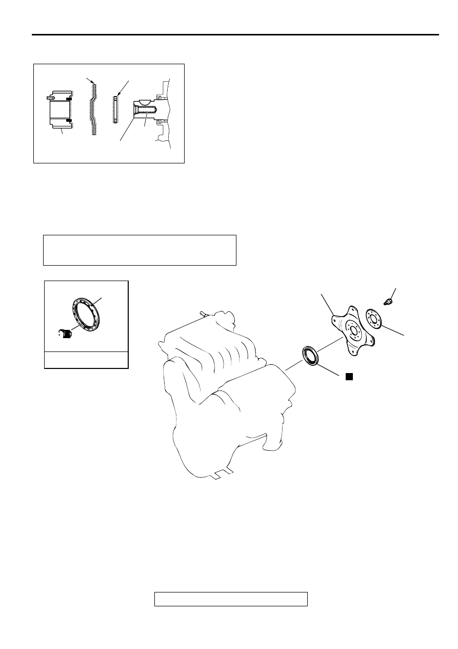
>>B<< CRANKSHAFT SPACER/CRANKSHAFT SENSING 
BLADE/CRANKSHAFT SPROCKET INSTALLATION
To prevent the crankshaft pulley mounting bolt from loosening, 
degrees or clean the crankshaft, the crankshaft spacer, the 
crankshaft sensing blade and the crankshaft at the shown 
positions.

CR AN KSH A FT REA R  O IL SEAL

REMOVAL AND INSTALLATION

M1112003700112

Required Special Tools:

MD998718: Crankshaft Rear Oil Seal Installer

MD998781: Flywheel Stopper

ACX01536 AB

CRANKSHAFT

CRANKSHAFT

SPACER

CRANKSHAFT

SENSING BLADE

CRANKSHAFT

SPROCKET

SHADED PART : DEGREASE

CLEANING

Pre-removal and Post-installation Operation

Transaxle Assembly Removal and Installation (Refer to 
GROUP 23A, Transaxle Assembly

P.23A-290

.)

AC004835

3

ENGINE OIL

72 – 76 N·m
53 – 56 ft-lb

1

2

3

N

AB

REMOVAL STEPS

<<A>>

>>B<<

1.

ADAPTER PLATE

<<A>>

>>B<<

2.

DRIVE PLATE

>>A<<

3.

CRANKSHAFT REAR OIL SEAL

REMOVAL STEPS (Continued)

CRANKSHAFT REAR OIL SEAL

TSB Revision

ENGINE MECHANICAL <3.0L>

11C-26

REMOVAL SERVICE POINT

<<A>> ADAPTER PLATE/DRIVE PLATE REMOVAL
Use special tool MB998781 to secure the drive plate, and 
remove the bolts.

INSTALLATION SERVICE POINTS

>>A<< CRANKSHAFT REAR OIL SEAL INSTALLATION
1. Apply a small amount of engine oil to the entire 

circumference of the oil seal lip.

2. Use special tool MD998718 to tap in the oil seal as shown in 

the illustration.

>>B<< DRIVE PLATE/ADAPTER PLATE INSTALLATION
Use special tool MD998781 to hold the drive plate in the same 
manner as removal. Then install the bolts.

ACX00296 AB

MD998781

ACX00356 AB

MD998718

ACX00296 AB

MD998781

CYLINDER HEAD GASKET

TSB Revision

ENGINE MECHANICAL <3.0L>

11C-27

CYLIN D ER  H EA D G A SKET

REMOVAL AND INSTALLATION

M1112004000116

Pre-removal and Post-installation Operation

Engine Coolant Draining and Refilling [Refer to GROUP 
00, Maintenance Service 

 Engine Coolant (Change) 

P.00-50

.]

Timing Belt Removal and installation (Refer to 

P.11C-29

.)

Generator Removal and Installation (Refer to GROUP16, 
Generator 

P.16-14

.)

Intake Manifold Removal and installation (Refer to 
GROUP 15, Intake Manifold 

P.15-10

.)

Exhaust Manifold Removal and Installation (Refer to 
GROUP 15, Exhaust Manifold 

P.15-16

.)

Water Inlet Pipe Removal and Installation (Refer to 
GROUP 14, Water Hose and Water Pipe 

P.14-23

.)

AC004838AB

12 – 15 N·m
106 – 133 in-lb

3.4 N·m
30 in-lb

3.4 N·m
30 in-lb

<COLD ENGINE>
103 – 113 N·m 

 0 N·m 

 103 – 113 N·m

76 – 83 ft-lb 

 0 in-lb 

 76 – 83 ft-lb

1

2

2

3

4

6

4

6

7

9

9

10

N

<COLD ENGINE>
103 – 113 N·m 

 0 N·m 

 103 – 113 N·m

76 – 83 ft-lb 

 0 in-lb 

 76 – 83 ft-lb

5

8

REMOVAL STEPS

1.

BREATHER HOSE

2.

BLOW-BY HOSE

3.

PCV HOSE

4.

SPARK PLUG CABLE

5.

BATTERY CABLE 
CONNECTION

REMOVAL STEPS (Continued)

CYLINDER HEAD GASKET

TSB Revision

ENGINE MECHANICAL <3.0L>

11C-28

Required Special Tool:

MD998051: Cylinder Head Bolt Wrench

REMOVAL SERVICE POINT

<<A>> CYLINDER HEAD ASSEMBLY REMOVAL
Using special tool MD998051, loosen the cylinder head bolts in 
two or three steps in the order of the numbers shown in the 
illustration, then remove the cylinder head assembly.

INSTALLATION SERVICE POINTS

>>A<< CYLINDER HEAD GASKET INSTALLATION
1. Wipe off all oil and grease from the gasket mounting 

surface.

2. Match the shapes of the cylinder head holes with their 

respective cylinder head gasket holes.

>>B<< CYLINDER HEAD ASSEMBLY INSTALLATION

CAUTION

Be careful that no foreign material gets into the cylinder, 
coolant passages or oil passages. Engine damage may 
result.
1. Use a scraper to clean the gasket surface of the cylinder 

head assembly.

6.

ROCKER COVER

7.

TIMING BELT REAR COVER

8.

BATTERY CABLE 
CONNECTION

<<A>>

>>B<<

9.

CYLINDER HEAD ASSEMBLY

>>A<<

10. CYLINDER HEAD GASKET

REMOVAL STEPS (Continued)

AC001732

7

3

6

2

5

4

8

1

5

1

8

4

7

6

2

3

EXHAUST SIDE

EXHAUST SIDE

INTAKE SIDE

FRONT OF 
ENGINE

MD998051

AB


Content   ..  58  59  60  61   ..