Mitsubishi Galant. Manual - part 19


  Index      Mitsubishi     Mitsubishi Galant - service repair manual 2001 year


Search            


Content   ..  17  18  19  20   ..


Mitsubishi Galant. Manual - part 19


HOW TO DIAGNOSE

TSB Revision

GENERAL <ELECTRICAL>

00E-11

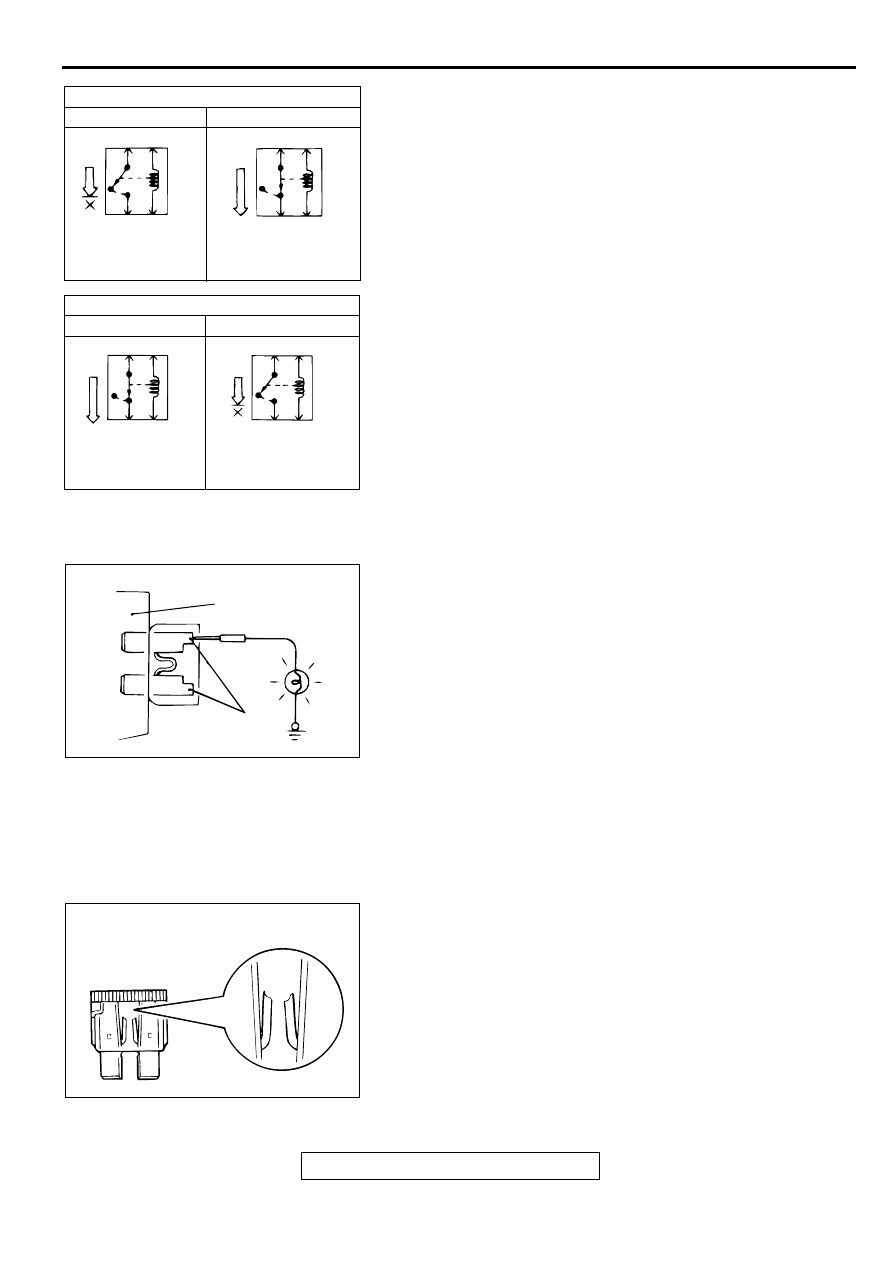
3. Relays may be classified as the normally open-type or the 

normally closed-type, depending on their contact 
construction.

CHECKING FUSES

M1001005000033

A blade type fuse has test taps provided to allow checking of 
the fuse itself without removing it from the fuse block. The fuse 
is okay if the test light comes on when its one lead is connected 
to the test taps (one at a time) and the other lead is grounded. 
Remember to turn the ignition switch to ON to ensure all 
circuits are live.

CAUTIONS IN EVENT OF BLOWN FUSE

When a fuse is blown, there are two probable causes. One is 
that it is blown due to flow of current exceeding its rating. The 
other is that it is blown due to repeated on/off current flowing 
through it. Which of the two causes is responsible can be easily 
determined by visual check as described below.
1. Fuse blown due to current exceeding rating

The illustration shows the state of a fuse blown due to this 
cause. In this case, do not replace the fuse with a new one 
hastily since a current heavy enough to blow the fuse has 
flowed through it. First, check the circuit for shorts and check 
for abnormal electric parts. After correcting shorts or 
replacing parts, use only a fuse of the same capacity as a 
replacement. Never use a fuse of larger capacity than the 
original fuse. If a larger capacity fuse is used, electric parts 
or wiring could be damaged.

ACX00949AB

NORMAL OPEN (NO) TYPE

DEENERGIZED STATE ENERGIZED STATE

CURRENT FLOWS

CURRENT DOES
NOT FLOW

ACX00950AB

NORMAL CLOSED (NC) TYPE

DEENERGIZED STATE ENERGIZED STATE

CURRENT FLOWS

CURRENT DOES
NOT FLOW

ACX00951AB

FUSE BLOCK

TEST TAPS

ACX00952 AB

STATE OF FUSE BLOWN DUE TO
OVERCURRENT

HOW TO DIAGNOSE

TSB Revision

GENERAL <ELECTRICAL>

00E-12

2. Fuse blown due to repeated turning current on and off

The illustration shows the state of a fuse blown due to 
repeated current on/off. Normally, this type of problem 
occurs after a fairly long period of use and is less frequent 
than the above. In this case, simply replace with a new fuse 
of the same capacity.

CABLES AND WIRES CHECK

M1001005100030

1. Check connections for looseness, rust, and stains.

2. Check terminals and wires for corrosion by battery 

electrolyte, etc.

3. Check terminals and wires for open circuit or impending 

open circuit.

4. Check wire insulation and coating for damage, cracks and 

wear.

5. Check conductive parts of terminals for contact with other 

metallic parts (vehicle body and other parts).

6. Check grounding parts to verify that there is complete 

continuity between attaching bolt(s) and vehicle body.

7. Check for incorrect wiring.

8. Check that harnesses are secured to prevent contact with 

sharp edges and corners or hot parts (exhaust manifold, 
pipe, etc.).

9. Check that harnesses are secured firmly to provide enough 

clearance from the fan pulley, fan belt, and other rotating or 
moving parts.

10.Check that the harness between fixed parts (such as the 

vehicle body) and vibrating parts (such as the engine) are 
long enough to allow for vibration and movement.

BATTERY HANDLING

M1001005200037

WARNING

Battery posts, terminals and related accessories 
contain lead and lead compounds. WASH HANDS 
AFTER HANDLING.

When checking or servicing does not require power from the 
vehicle battery, be sure to disconnect the cable from the battery 
(

) terminal. This will prevent problems that could be caused by 

a short circuit. Disconnect the (

) battery terminal first and 

reconnect it last.

ACX00953 AB

STATE OF FUSE BLOWN DUE TO
THERMAL FATIGUE

ACX00954 AB

ACX00955AB

AC000017

HOW TO DIAGNOSE

TSB Revision

GENERAL <ELECTRICAL>

00E-13

GENERAL ELECTRICAL SYSTEM CHECK

M1001005300034

A circuit consists of the power supply, switch, relay, load, 
ground, etc. There are various methods to check a circuit 
including an overall check, voltage check, short-circuit check, 
and continuity check. Each of the methods briefly described 
below apply only to circuits similar to the illustration.
1. VOLTAGE CHECK

(1) Ground one lead wire of the test light. If a voltmeter is 

used instead of the test light, ground the grounding side 
lead wire.

(2) Connect the other lead wire of the test light to the power 

side terminal of the switch connector. The test light 
should come on or the voltmeter should indicate a 
voltage.

(3) Then, connect the test light or voltmeter to the motor 

connector. The test light should not come on, or the 
voltmeter should indicate no voltage. When the switch is 
turned on in this state, the test light should come on, or 
the voltmeter should indicate a voltage, with motor 
starting to run.

(4) The circuit illustrated here is normal. If there is any 

problem, such as the motor failing to run, check voltages 
beginning at the connector nearest to the motor until the 
faulty part is identified.

2. SHORT-CIRCUIT CHECK

Because the fuse has blown, it is probable that there is a 
short circuit. Follow the procedures below to narrow down 
the short-circuit location.

STEP 1. Remove the blown fuse and connect the test light 
across the fuse terminals (Switch: OFF).
Q: Does the test light illuminate?

YES : Short-circuit exists between the fuse block and the 

switch.Repair the harness between the fuse block 
and the switch. 

NO :  Go to Step 2.

ACX00956AB

POWER SUPPLY

FUSE

SWITCH

MOTOR

(3)

ON  (2)

OFF

(1)

TEST LIGHT
(OR
VOLTMETER)

ACX00957AB

POWER SUPPLY

SWITCH

OFF

ILLUMINATION
LIGHT

TEST
LIGHT

FUSE BLOCK
(REMOVE
THE FUSE)

SHORT-CIRCUIT
LOCATION

HOW TO DIAGNOSE

TSB Revision

GENERAL <ELECTRICAL>

00E-14

STEP 2. Switch on the switch and disconnect the 
illumination light connector.
Q: Does the test light illuminate?

YES : Short-circuit exists between the switch and the 

connector. Repair the harness between the switch 
and the connector. 

NO :  Short-circuit exists between the connector and the 

illumination light. Repair the harness between the 
switch and the connector.

ACX00958AB

POWER SUPPLY

SWITCH

ON

ILLUMINATION
LIGHT

TEST
LIGHT

FUSE BLOCK
(REMOVE
THE FUSE)

DISCONNECT
THE LOAD

SHORT-CIRCUIT
LOCATION

ACX00959AB

POWER SUPPLY

SWITCH

ON

ILLUMINATION
LIGHT

TEST
LIGHT

FUSE BLOCK
(REMOVE
THE FUSE)

DISCONNECT
THE LOAD

SHORT-CIRCUIT
LOCATION


Content   ..  17  18  19  20   ..