Mitsubishi Galant. Manual - part 18


  Index      Mitsubishi     Mitsubishi Galant - service repair manual 2001 year


Search            


Content   ..  16  17  18  19   ..


Mitsubishi Galant. Manual - part 18


HOW TO DIAGNOSE

TSB Revision

GENERAL <ELECTRICAL>

00E-7

INSPECTION

M1001004600032

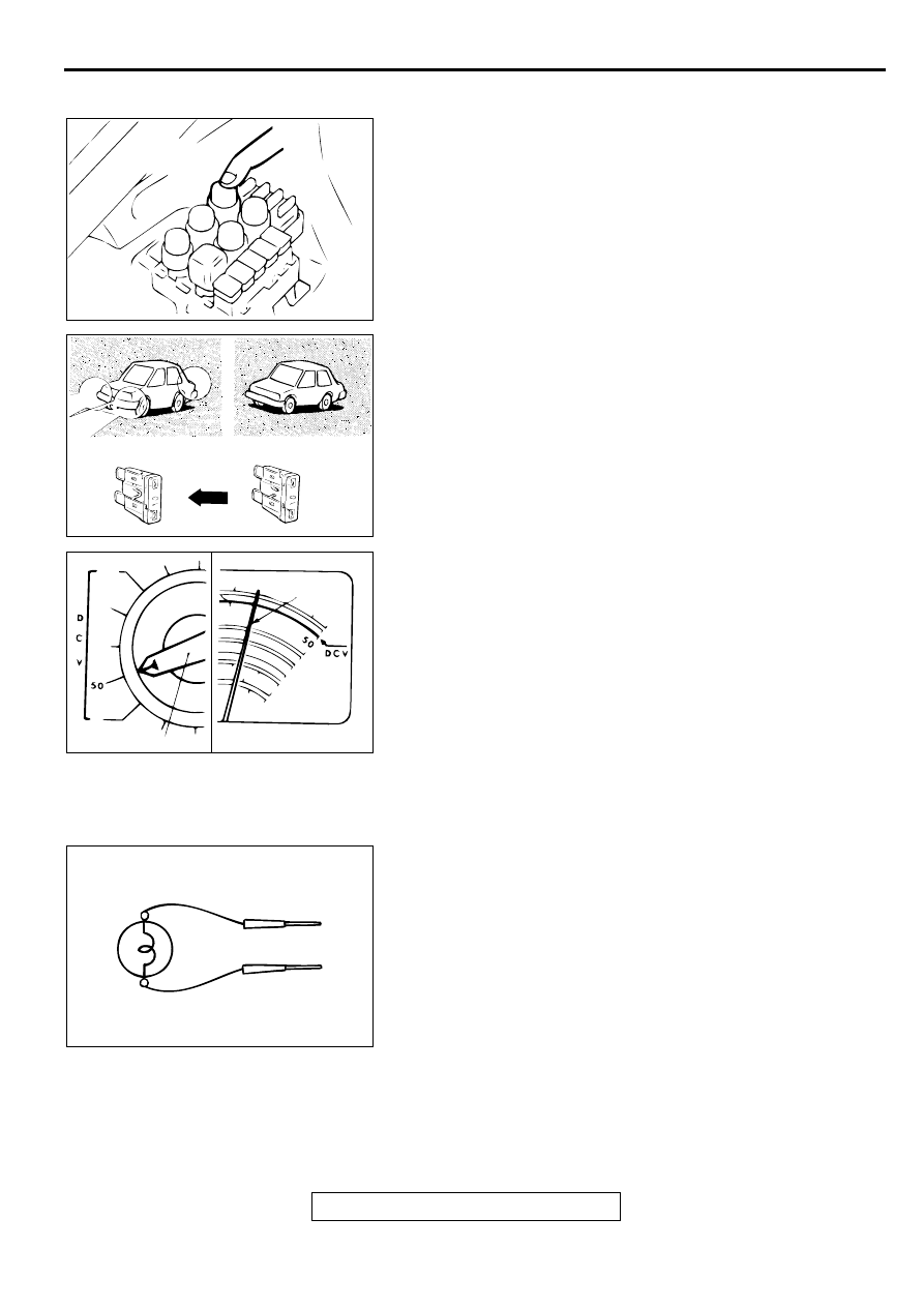
1. Sight and sound checks

Check relay operation, blower motor rotation, light 
illumination, etc. Listen for a "click" when a relay cover is 
pushed down.

2. Simple checks

For example, if a headlight does not come on and a faulty 
fuse or poor grounding is suspected. Replace the fuse with a 
new one. Or use a jumper wire to ground the light to the 
body. Determine which part(s) is/are responsible for the 
problem.

3. Checking with instruments

Use an appropriate instrument in an adequate range and 
read the indication correctly.

INSPECTION INSTRUMENTS

M1001004700039

For inspection, use the following instruments:
1. Test lights

A test light consists of a 12V bulb and lead wires. It is used 
to check voltages or short circuits.

ACX00936 AB

CLICK

ACX00937

ACX00938AB

SELECTOR KNOB

POINTER

ACX00939

HOW TO DIAGNOSE

TSB Revision

GENERAL <ELECTRICAL>

00E-8

2. Self-powered test light

A self-powered test light consists of a bulb, battery and lead 
wires connected in series. It is used to check continuity or 
grounding.

3. Jumper wire

CAUTION

Never use a jumper wire to connect a power supply 
directly to a load.

A jumper wire is used to close an open circuit. 

4. Voltmeter

A voltmeter is used to measure the circuit voltage. Normally, 
the positive (red lead) probe is applied to the point of voltage 
measurement and the negative (black lead) probe to the 
body ground. Use a digital voltmeter to check for voltage 
drop before or after a component.

5. Ohmmeter

An ohmmeter is used to check continuity or measure 
resistance of a switch or coil. If the measuring range has 
been changed, the zero point must be adjusted before 
measurement.

ACX00940

ACX00941

ACX00942AB

RED LEAD WIRE

POWER LINE

BLACK LEAD WIRE

GROUND

ACX00943

HOW TO DIAGNOSE

TSB Revision

GENERAL <ELECTRICAL>

00E-9

CHECKING SWITCHES

M1001004800036

In a circuit diagram, a switch is shown in the idle state.
1. Normally open or normally closed switch

Switches are classified into those which open the circuit and 
those which close the circuit when off.

2. Switch connection

This figure illustrates a complex switch. The continuity 
between terminals at each position is as indicated in the 
table below.

SWITCH
POSITION

TESTER
CONNECTION

SPECIFIED 
CONNECTION

OFF

1st stage

1

5

6

Continuity

2nd stage

1

4

6

Continuity

3rd stage

1

3

6

Continuity

4th stage

1

2

6

Continuity

ACX00944AB

CURRENT
FLOWS

CURRENT DOES
NOT FLOW

CURRENT DOES
NOT FLOW

CURRENT FLOWS

OFF

OFF

ON

ON

NORMAL OPEN (NO) TYPE

NORMAL CLOSED (NC) TYPE

ACX00945 AB

6

OFF

5

4

3

2

1

1ST 2ND 3RD 4TH STAGE

HOW TO DIAGNOSE

TSB Revision

GENERAL <ELECTRICAL>

00E-10

CHECKING RELAYS

M1001004900033

NOTE: The deenergized state means that no current is flowing 
through the coil. The energized state means that current is 
flowing through the coil.
When a normal closed relay as illustrated here is checked, 
there should be continuity between terminals 1 and 2 and 
between terminals 3 and 4 when the relay is deenergized. 
There should be no continuity between terminals 3 and 4 when 
the battery voltage and ground are applied to terminals 1 and 2.

1. When current flows through the coil of a relay, its core is 

magnetized to attract the iron piece, closing (ON) the 
contact at the tip of the iron piece. When the coil current is 
turned off, the iron piece returns to its original position by a 
spring, opening the contact (OFF).

2. By using a relay, a heavy current can be turned on and off by 

a switch using much less current. For example, in the circuit 
shown here, when the switch is turned on (closed), current 
flows to the coil of the relay. Then, its contact is turned on 
(closed) and the light comes on. The current flowing through 
the switch is much less than that for the light.

ACX00946AB

4

3

2

1

4

3

2

1

NORMAL CLOSED (NC) TYPE

DEENERGIZED STATE ENERGIZED STATE

CURRENT FLOWS

CURRENT DOES
NOT FLOW

ACX00947AB

COVER

SPRING

IRON
CORE

COIL

IRON
PIECE

CONTACT

ACX00948 AB

POWER SUPPLY

FUSE

LIGHT

RELAY

SWITCH
ON

OFF

ON

OFF


Content   ..  16  17  18  19   ..