Mitsubishi Galant 9G. Manual - part 694
MULTIPORT FUEL INJECTION (MFI) DIAGNOSIS
TSB Revision
MULTIPORT FUEL INJECTION (MFI) <2.4L ENGINE>
13A-218
.
CIRCUIT OPERATION
• A voltage corresponding to the oxygen concen-
tration in the exhaust gas is sent to the PCM (ter-
minal No. 92) from the output terminal (terminal
No. 4) of the cylinder 1, 4 heated oxygen sensor
(front).
• Terminal No. 2 of the cylinder 1, 4 heated oxygen
sensor (front) is grounded with PCM (terminal
No. 69).
.
TECHNICAL DESCRIPTION
• The cylinder 1, 4 heated oxygen sensor (front)
detects the concentration of oxygen in the
exhaust gas; it converts those data to voltage,
and inputs the resulting signals to the PCM.
• When the cylinder 1, 4 heated oxygen sensor
(front) begins to deteriorate, the heated oxygen
sensor signal response becomes poor.
• The PCM forcibly varies the air/fuel mixture to
make it leaner and richer, and checks the
response speed of the cylinder 1, 4 heated oxy-
gen sensor (front). In addition, the PCM also
checks for an open circuit in the cylinder 1, 4
heated oxygen sensor (front) output line.
.
DESCRIPTIONS OF MONITOR METHODS
Cylinder 1, 4 heated oxygen sensor (front) output
voltage is over specified range.
.
MONITOR EXECUTION
Continuous
.
MONITOR EXECUTION CONDITIONS
(Other monitor and Sensor)
Other Monitor (There is no temporary DTC stored
in memory for the item monitored below)
• Heated oxygen sensor heater (front) monitor
• Misfire monitor
• Fuel system monitor
Sensor (The sensor below is determined to be
normal)
• Mass airflow sensor
• Engine coolant temperature sensor
• Intake air temperature sensor
• Barometric pressure sensor
• Throttle position sensor
• Accelerator pedal position sensor
.
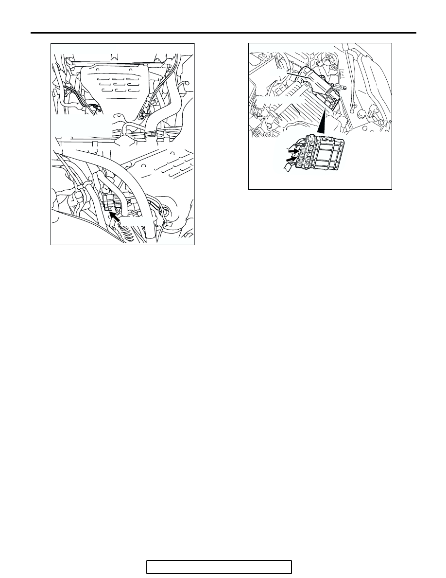
AK303820AB
CONNECTOR: B-37
CYLINDER 1, 4
HEATED OXYGEN
SENSOR (FRONT)
B-37 (GR)
AK303013
CONNECTORS: B-21, B-22
PCM
AB
AIR CLEANER
B-22 (B)
B-21 (B)