Mitsubishi Galant 9G. Manual - part 692


  Index      Mitsubishi     Mitsubishi Galant 9G - service repair manual


Search            


Content   ..  690  691  692  693   ..


Mitsubishi Galant 9G. Manual - part 692


MULTIPORT FUEL INJECTION (MFI) DIAGNOSIS

TSB Revision

MULTIPORT FUEL INJECTION (MFI) <2.4L ENGINE>

13A-210

STEP 15. Test the OBD-II drive cycle.
(1) Carry out a test drive with the drive cycle pattern. Refer to 

Diagnostic Function 

− OBD-II Drive Cycle − Procedure 6 − 

Other Monitor 

P.13A-6

.

(2) Check the diagnostic trouble code (DTC).
Q: Is DTC P0130 set?

YES : Retry the troubleshooting.
NO :  The inspection is complete.

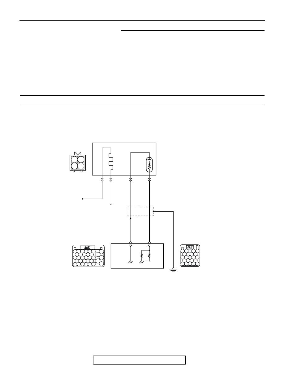
DTC P0131: Cylinder 1, 4 Heated Oxygen Sensor Circuit Low Voltage (sensor 1)

100

99

92

91

93 94 95

96 97 98

101 102 103 104

105 106 107 108

109 110 111 112 113

52

51

53 54 55 56

57

58 59 60 61 62

63

64 65 66 67 68 69

70

71 72 73 74 75

76

77 78 79 80 81 82

83

AK303819

1

2

3

4

BLA

CK

BLUE

BLA

CK

TO PCM

FROM MFI RELAY

PINK

69

92

4

3

1

CYLINDER 1, 4
HEATED OXYGEN
SENSOR (FRONT)

POWERTRAIN CONTROL
MODULE (PCM)

B-37

MU802665

2

B-22

Cylinder 1, 4 Heated Oxygen Sensor (front) Circuit

B-21

MULTIPORT FUEL INJECTION (MFI) DIAGNOSIS

TSB Revision

MULTIPORT FUEL INJECTION (MFI) <2.4L ENGINE>

13A-211

.

CIRCUIT OPERATION

• A voltage corresponding to the oxygen concen-

tration in the exhaust gas is sent to the PCM (ter-
minal No. 92) from the output terminal (terminal 
No. 4) of the cylinder 1, 4 heated oxygen sensor 
(front).

• Terminal No. 2 of the cylinder 1, 4 heated oxygen 

sensor (front) is grounded with PCM (terminal 
No. 69).

.

TECHNICAL DESCRIPTION

• The cylinder 1, 4 heated oxygen sensor (front) 

detects the concentration of oxygen in the 
exhaust gas; it converts those data to voltage, 
and inputs the resulting signals to the PCM.

• When the cylinder 1, 4 heated oxygen sensor 

(front) begins to deteriorate, the heated oxygen 
sensor signal response becomes poor.

• The PCM forcibly varies the air/fuel mixture to 

make it leaner and richer, and checks the 
response speed of the cylinder 1, 4 heated oxy-
gen sensor (front). In addition, the PCM also 
checks for an open circuit in the cylinder 1, 4 
heated oxygen sensor (front) output line.

.

DESCRIPTIONS OF MONITOR METHODS

Cylinder 1, 4 heated oxygen sensor (front) output 

voltage stays low when air/fuel ratio is forced to 
be rich. The above procedure is repeated when 
oxygen sensor is inactive.

.

MONITOR EXECUTION

Continuous

.

MONITOR EXECUTION CONDITIONS 
(Other monitor and Sensor)

Other Monitor (There is no temporary DTC stored 

in memory for the item monitored below)

• Heated oxygen sensor heater (front) monitor

• Misfire monitor

• Fuel system monitor

Sensor (The sensor below is determined to be 

normal)

• Mass airflow sensor

• Engine coolant temperature sensor

• Intake air temperature sensor

• Barometric pressure sensor

• Throttle position sensor

• Accelerator pedal position sensor

.

AK303820AB

CONNECTOR: B-37

CYLINDER 1, 4
HEATED OXYGEN
SENSOR (FRONT)

B-37 (GR)

AK303013

CONNECTORS: B-21, B-22

PCM

AB

AIR CLEANER

B-22 (B)

B-21 (B)

MULTIPORT FUEL INJECTION (MFI) DIAGNOSIS

TSB Revision

MULTIPORT FUEL INJECTION (MFI) <2.4L ENGINE>

13A-212

DTC SET CONDITIONS
Logic Flow Chart

.

Check Conditions

• After 2 seconds or more pass from the time when 

the monitor determines normally for detecting an 
open circuit.

• Cylinder 1, 4 heated oxygen sensor (front) signal 

voltage has continued to be 0.2 volt or lower.

• Engine coolant temperature is higher than 76°C 

(169

°F).

• Mass airflow sensor output is 6 g/sec or more.

• At least 20 seconds have passed since fuel shut 

off control was canceled.

• Monitoring time: 8 seconds.

START

V

F

 > =4.5V

2secs HAS PASSED

YES

YES

YES

NO

NO

NO

MALFUNCTION

MONITORING

CONDITIONS

YES

NO

MONITORING

CONDITIONS

+5V ON

AK401409

V

F

 < 0.2V

8secs HAS PASSED

YES

YES

NO

NO

END

MALFUNCTION

GOOD

MODULATE A/F CONDITION TO RICH

MULTIPORT FUEL INJECTION (MFI) DIAGNOSIS

TSB Revision

MULTIPORT FUEL INJECTION (MFI) <2.4L ENGINE>

13A-213

Judgement Criteria

• Making the air/fuel ratio 15 percent richer for 8 

seconds does not result in raising the heated oxy-
gen sensor (front) output voltage beyond 0.2 volt.

.

OBD-II DRIVE CYCLE PATTERN

Refer to Diagnostic Function 

− OBD-II Drive Cycle − 

Procedure 6 

− Other Monitor 

P.13A-6

.

.

TROUBLESHOOTING HINTS (The most 
likely causes for this code to be set are:)

• Cylinder 1, 4 heated oxygen sensor (front) failed.

• Short circuit in cylinder 1, 4 heated oxygen sen-

sor (front) output line.

• Connector damage.

• PCM failed.

DIAGNOSIS

Required Special Tools:

• MB991958: Scan tool (MUT-III Sub Assembly)

• MB991824: V.C.I.

• MB991827: USB Cable

• MB991910: Main Harness A

• MB991316: Test Harness

STEP 1. Using scan tool MB991958, check data list item 39: 
Cylinder 1, 4 Heated Oxygen Sensor (front).

CAUTION

To prevent damage to scan tool MB991958, always turn the 
ignition switch to the "LOCK" (OFF) position before con-
necting or disconnecting scan tool MB991958.
(1) Connect scan tool MB991958 to the data link connector.
(2) Start the engine and run at idle.
(3) Set scan tool MB991958 to the data reading mode for item 

39, Cylinder 1, 4 Heated Oxygen Sensor (front).

• Warm up the engine. When the engine is revved, the 

output voltage should measure 0.6 to 1.0 volt.

• Warm up the engine. When the engine is idling, the out-

put voltage should repeat 0.4 volt and 0.6 to 1.0 volt 
alternately.

(4) Turn the ignition switch to the "LOCK" (OFF) position.
Q: Is the sensor operating properly?

YES : It can be assumed that this malfunction is intermittent. 

Refer to GROUP 00, How to Use 
Troubleshooting/Inspection Service Points 

− How to 

Cope with Intermittent Malfunctions 

P.00-14

.

NO :  Go to Step 2.

AK303804AB

MB991910

DATA LINK
CONNECTOR

MB991824

MB991827


Content   ..  690  691  692  693   ..