Mitsubishi Galant 9G. Manual - part 575


  Index      Mitsubishi     Mitsubishi Galant 9G - service repair manual


Search            


Content   ..  573  574  575  576   ..


Mitsubishi Galant 9G. Manual - part 575


ON-VEHICLE SERVICE

TSB Revision

AUTOMATIC TRANSAXLE

23A-378

KEY INTERLOCK AND SHIFT LOCK MECHANISM 
CHECK

M1232003100216

1. Carry out the following inspection.

2. When any of the above checks are not normal, adjust the 

key interlock cable and shift lock cable unit in following 
procedure.

(1) Remove the front floor console. (Refer to GROUP 52A 

− 

Floor Console Assembly 

P.52A-9

).

(2) Shift selector lever to "P" position.
(3) Turn the ignition key to "LOCK" (OFF) position.
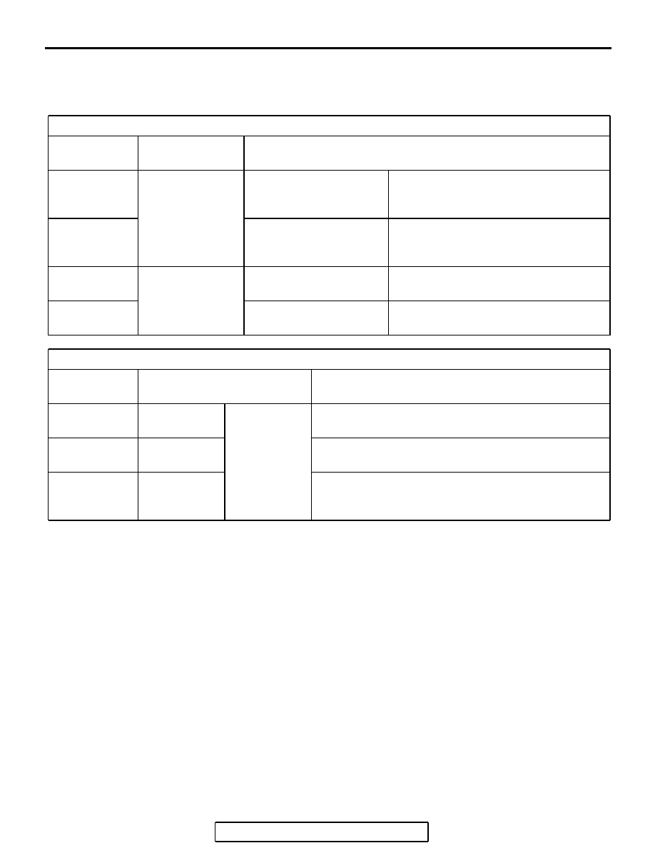
KEY INTERLOCK SIDE

INSPECTION 
PROCEDURE

INSPECTION 
REQUIREMENT

INSPECTION ITEM (NORMAL CONDITION)

1

Brake pedal: 
Depressed

Ignition key position: 
"LOCK" (OFF) or removed

Unable to push in the selector lever push 
button and move the lever out of the "P" 
position.

2

Ignition key position: 
"ACC"

Able to push in the selector lever push 
button, move the lever out of the "P" 
position, and shift to any position.

3

Brake pedal: Not 
depressed

Selector lever: Other than 
"P" position

Unable to turn the ignition key to the 
"LOCK" (OFF) position.

4

Selector lever: "P" position Able to turn the ignition key to the 

"LOCK" (OFF) position.

SHIFT LOCK SIDE

INSPECTION 
PROCEDURE

INSPECTION CONTENTS

CHECK DETAILS (NORMAL CONDITION)

1

Brake pedal: 
Not depressed

Ignition key 
position: "ACC"

When the selector lever push button is depressed, the 
selector lever can not be shifted out of the "P" position.

2

Brake pedal: 
Depressed

When the selector lever push button is depressed, the 
selector lever can be shifted smoothly to other position.

3

Brake pedal: 
Not depressed

When the selector lever push button is depressed, the 
selector lever can be shifted smoothly from the "R" 
position to the "P" position.

ON-VEHICLE SERVICE

TSB Revision

AUTOMATIC TRANSAXLE

23A-379

(4) Loosen the bolt fixing the shift lock cable unit, push the 

lever in direction B and the unit in direction C and tighten 
the bolt at the standard torque.

Tightening torque: 5.0 

± 1.0 Nm (44 ± 9 in-lb)

(5) Lift the lock guide of the key interlock cable and then 

unlock it.

(6) Lower the lock guide of the key interlock cable and then 

lock it.
NOTE: The key interlock cable is adjusted according to 
the lock position (cap push state) at this time. Readjust 
the lock position if key interlocking operations malfunction 
after locking.

3. After adjustment, re-check the operations. Replace the key 

interlock cable and shift lock cable unit if operations are 
defective. (Refer to 

P.23A-385

).

TRANSAXLE CONTROL CABLE ADJUSTMENT

M1231028000064

1. Move the selector lever to the "N" position.
2. Loosen the upper control lever adjusting nut.
3. Gently push the transaxle control cable in the direction of the 

arrow, and then tighten the adjusting nut.

Tightening torque: 12 

± 2 Nm (107 ± 17 in-lb)

4. Check that the transaxle shifts to the correct range 

corresponding to the position of the selector lever, and that it 
functions correctly in that range.

AC000004AG

LOCK

UNLOCK

LOCK GUIDE

KEY INTERLOCK CABLE

CAP

LEVER

FIXING BOLT

SHIFT LOCK CABLE UNIT

C

A

B

VIEW A

AC305881

AC305532

AC305679

<F4A4B>

MANUAL CONTROL LEVER

MANUAL CONTROL LEVER

<F4A5A>

ADJUSTING NUT

12 ± 2 N·m
107 ± 17 in-lb

ADJUSTING NUT

12 ± 2 N·m
107 ± 17 in-lb

AE

TRANSAXLE CONTROL

TSB Revision

AUTOMATIC TRANSAXLE

23A-380

TRANSAXLE CONTROL

REMOVAL AND INSTALLATION

M1231006600585

WARNING

When removing and installing the transaxle control cable and shift lock cable unit, be 
careful not to hit the SRS-ECU.

When removing and installing the front passenger seat, be sure to carry out accuracy 
check occupant classification sensor after the seat has been installed in the vehicle. 
(Refer to GROUP 52B, On-Vehicle Service 

P.52B-355

.)

AC305533AB

1

12 ± 2 N·m
107 ± 17 in-lb

<F4A5A>

<F4A4B>

2

2

5

6

8

3

12 ± 2 N·m
102 ± 22 in-lb

5.0 ± 1.0 N·m
44 ± 9 in-lb

12 ± 2 N·m
102 ± 22 in-lb

4

7

7

TRANSAXLE CONTROL CABLE 

ASSEMBLY REMOVAL STEPS

AIR DUCT AND AIR CLEANER 

ASSEMBLY (REFER TO GROUP 15 

P.15-4

.)

BATTERY AND BATTERY TRAY

POWERTRAIN CONTROL MODULE 

(PCM) (REFER TO GROUP 13A 

P.13A-1140

.)

HEATER UNIT  AND DECK 

CROSSMEMBER ASSEMBLY 

(REFER TO GROUP 55, HEATER 

UNIT, HEATER CORE, BLOWER 

ASSEMBLY AND EVAPORATOR 
UNIT 

P.55A-267

.)

>>B<<

1.

ADJUSTING NUT

>>B<<

2.

TRANSAXLE CONTROL CABLE 

ASSEMBLY CONNECTION 

(TRANSAXLE SIDE)

>>A<<

3.

SHIFT LOCK CABLE UNIT

4.

TRANSAXLE CONTROL CABLE 

ASSEMBLY CONNECTION 

(SELECTOR LEVER ASSEMBLY 

SIDE)

5.

TRANSAXLE CONTROL CABLE 

ASSEMBLY
SELECTOR LEVER ASSEMBLY 

ASSEMBLY REMOVAL STEPS

FLOOR CONSOLE (REFER TO 

GROUP 52A, FLOOR CONSOL 
ASSEMBLY 

P.52A-9

)

>>A<<

3.

SHIFT LOCK CABLE UNIT

4.

TRANSAXLE CONTROL CABLE 

ASSEMBLY CONNECTION 

(SELECTOR LEVER ASSEMBLY 

SIDE)

6.

A/T SELECTOR LEVER POSITION 

ILLUMINATION LIGHT HARNESS 

CONNECTOR <VEHICLES WITHOUT 

SPORT MODE>, 

SHIFT SWITCH ASSEMBLY 

HARNESS CONNECTOR <VEHICLES 

WITH SPORT  MODE>

TRANSAXLE CONTROL CABLE 
ASSEMBLY REMOVAL STEPS


TRANSAXLE CONTROL

TSB Revision

AUTOMATIC TRANSAXLE

23A-381

INSTALLATION SERVICE POINTS

.

>>A<< SHIFT LOCK CABLE UNIT INSTALLATION

1. Selector lever to "P" position.
2. Turn the ignition key to "LOCK" (OFF) position.
3. Install the rod of the shift lock cable unit to the lock cam, 

push the lever in direction A, push the shift lock cable unit in 
direction B and tighten the fixing bolt at the standard torque.

Tightening torque: 5.0 

± 1.0 Nm (44 ± 9 in-lb)

4. Check the selector lever operation.(Refer to 

P.23A-377

).

.

>>B<< TRANSAXLE CONTROL CABLE 
ASSEMBLY (TRANSAXLE SIDE)/ADJUSTING NUT 
INSTALLATION

1. Place the selector lever and manual control lever in the "N" 

position.

2. Place the cable stud into the manual control lever slot and 

install the nut loosely. Gently push the transaxle control 
cable into the manual control lever slot until the cable is taut. 
Tighten the nut to the specified torque.

Tightening torque: 12 

± 2 Nm (107 ± 17 in-lb)

INSPECTION

M1231030000094

Check the cable assembly for function and for damage.

7.

HARNESS CILP CONNECTION

8.

SELECTOR LEVER ASSEMBLY

SELECTOR LEVER ASSEMBLY 

ASSEMBLY REMOVAL STEPS


AC308762

SHIFT LOCK 
CABLE UNIT

AC

LOCK CAM

LEVER

FIXING BOLT

ROD

A

B

AC305881

AC305532

AC305679

<F4A4B>

MANUAL CONTROL LEVER

MANUAL CONTROL LEVER

<F4A5A>

ADJUSTING NUT

12 ± 2 N·m
107 ± 17 in-lb

ADJUSTING NUT

12 ± 2 N·m
107 ± 17 in-lb

AE


Content   ..  573  574  575  576   ..