Mitsubishi Galant 9G. Manual - part 574


  Index      Mitsubishi     Mitsubishi Galant 9G - service repair manual


Search            


Content   ..  572  573  574  575   ..


Mitsubishi Galant 9G. Manual - part 574


ON-VEHICLE SERVICE

TSB Revision

AUTOMATIC TRANSAXLE

23A-374

6. Gently push the transaxle control cable in the direction of the 

arrow, until the cable is taut. Tighten the adjusting nut.

Tightening torque: 12 

± 2 Nm (107 ± 17 in-lb)

7. Check that the selector lever is in the "N" position.
8. Check that each position of the manual control lever 

matches each position of the selector lever using scan tool 
MB991958 (MUT-III sub assembly).

AUTOMATIC TRANSAXLE CONTROL 
COMPONENT CHECK

CRANKSHAFT POSITION SENSOR CHECK

M1231009000355

Refer to GROUP 13A <2.4L Engine>, Diagnosis 

− Inspection 

Procedure Using an Oscilloscope 

P.13A-1106

.

Refer to GROUP 13B <3.8L Engine>, Diagnosis 

− Inspection 

Procedure Using an Oscilloscope 

P.13B-1161

.

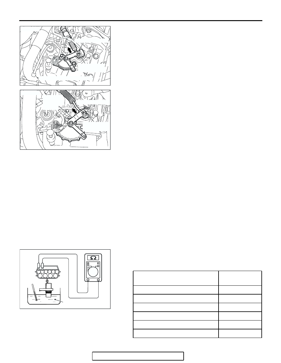
TRANSMISSION FLUID TEMPERATURE SENSOR 
CHECK

M1231021800133

1. Remove the transmission fluid temperature sensor.
2. Measure the resistance between terminals 1 and 2 of the 

transmission fluid temperature sensor connector.

Standard value:

AC305532

12 ± 2 N·m
107 ± 17 in-lb

MANUAL CONTROL LEVER

ADJUSTING NUT

AD

<F4A4B>

AC305881AD

12 ± 2 N·m
107 ± 17 in-lb

ADJUSTING NUT

MANUAL
CONTROL
LEVER

<F4A5A>

TRANSMISSION FLUID 
TEMPERATURE

RESISTANCE

0

°C (32°F)

16.7 

− 20.5 kΩ

20

°C (68°F)

7.3 

− 8.9 kΩ

40

°C (104°F)

3.4 

− 4.2 kΩ

60

°C (140°F)

1.9 

− 2.2 kΩ

80

°C (176°F)

1.0 

− 1.2 kΩ

100

°C (212°F)

0.57 

− 0.69 kΩ

AC210186

2

7

1

8

3

9

4

6

10

5

TRANSMISSION FLUID

AC

ON-VEHICLE SERVICE

TSB Revision

AUTOMATIC TRANSAXLE

23A-375

3. If the transmission fluid temperature sensor resistance is 

outside the specified range and the "N" range indicator light 
is flashing, replace the transmission fluid temperature 
sensor.
NOTE: The "N" range indicator light on the combination 
meter flashes when the temperature reaches approximately 
125

°

C (257

°

F) or greater, and then stops flashing when the 

temperature drops below approximately 115

°

C (238

°

F).

TRANSMISSION RANGE SWITCH CHECK

M1231021600117

 Refer to 

P.23A-372

.

STOPLIGHT SWITCH CHECK

M1231009100192

Refer to GROUP 35A, Brake Pedal 

− Brake Pedal Inspection 

P.35A-25

.

A/T CONTROL RELAY CHECK

M1231009300248

1. Remove the A/T control relay.

2. Use jumper wires to connect A/T control relay terminal 3 to 

the negative battery terminal and terminal 2 to the positive 
battery terminal.

3. Check for continuity between A/T control relay terminals 1 

and 4 when the jumper wires are connected to and 
disconnected from the battery.

4. If there is any problem with the A/T control relay, replace it.

JUMPER WIRE CONTINUITY BETWEEN TERMINALS 

NO.1 AND NO.4

Connected

Continuity

Disconnected

No continuity

AC306283

A/T 
CONTROL 
RELAY

RELAY BOX

AC

BATTERY

AC100115

1 2
3 4

FRONT OF VEHICLE

AJ

ON-VEHICLE SERVICE

TSB Revision

AUTOMATIC TRANSAXLE

23A-376

SOLENOID VALVE CHECK

M1231009400267

1. Use scan tool MB991958 (MUT-III sub assembly) to 

measure the transmission fluid temperature. The desired 
transmission fluid temperature setting for performing the 
solenoid valve check is 20

°C (68°F).

2. Remove the A/T control solenoid valve assembly connector.
3. Measure the resistance between the solenoid valve 

terminals.

4.  The measured resistance of the solenoid valve when the 

transmission fluid temperature is 20

°C (68°F) should match 

the specified resistance on the chart below.

Specified resistance:

5. If the solenoid valve resistance is within the specified range, 

check the power supply and the ground circuits.

6. If the solenoid valve resistance is not within the specified 

range, drain the transmission fluid and remove the valve 
body cover.

7. Disconnect the connector of any solenoid valves that are not 

within the specified range. 

8. Measure the resistance between terminals 1 and 2 of any 

solenoid valve that was not within the specified range.

Specified resistance: 2.7 

 3.4  [at 20°C (68°F)]

9. If the resistance is not within the specified range, replace the 

solenoid valve.

10.If the resistance is within the specified range, check the 

wiring harness between the affected A/T control solenoid 
valve assembly and the solenoid valve. If a problem is not 
found in the above steps, check the solenoid valve O-rings 
and replace them if necessary.

TERMINAL 
NO.

NAME

RESISTANCE

7 - 10

Torque converter clutch 
solenoid valve

2.7 

− 3.4 Ω [at 

20

°C (68°F)]

6 - 10

Low-reverse solenoid 
valve

4 - 9

Second solenoid valve

3 - 9

Underdrive solenoid 
valve

5 - 9

Overdrive solenoid valve

AC306288AB

A/T CONTROL
SOLENOID VALVE
ASSEMBLY

2

7

1

8

3

9

4

6

10

5

AC002219AD

LOW-
REVERSE
SOLENOID
VALVE

OVERDRIVE
SOLENOID
VALVE

TORQUE
CONVERTER
CLUTCH
SOLENOID

SECOND
SOLENOID
VALVE

UNDERDRIVE
SOLENOID
VALVE

AC100378

1
2

AB

ON-VEHICLE SERVICE

TSB Revision

AUTOMATIC TRANSAXLE

23A-377

SELECTOR LEVER OPERATION CHECK

M1231001300426

1. Apply the parking brake, and check that the selector lever 

moves smoothly and accurately to each position.

2. Check that the engine starts when the selector lever is at the 

"N" or "P" position, and that it does not start when the 
selector lever is in any other position.

3. Start the engine, release the parking brake, and check that 

the vehicle moves forward when the selector lever is moved 
from "N" position to "D," "3," "2" or "L" position or to 1st or 
2nd gear in Sports mode, and that the vehicle reverses 
when the selector lever is moved to "R" position.

4. Stop the engine.
5. Turn the ignition switch to the "ON" position, and check that 

the backup lamp illuminates when the selector lever is 
shifted from "P" position to "R" position.
NOTE: The A/T mis-operation prevention mechanism is pro-
vided so that the selector lever cannot be moved from the 
"P" position if the ignition switch is at a position other than 
the "LOCK" (OFF) position and the brake pedal is not 
depressed.

AC305529

THE SELECTOR LEVER MOVES WHEN THE 
BRAKE PEDAL IS DEPRESSED AND THE 
BUTTON IS PUSHED IN WITH THE IGNITION 
KEY IN ANY POSITION OTHER THAN THE
 "LOCK" (OFF) POSITION. 

THE SELECTOR LEVER MOVES WITHOUT 
PUSHING THE BUTTON.

THE SELECTOR LEVER MOVES WHEN THE 
BUTTON IS PUSHED.

AB

<VEHICLES WITHOUT 
  SPORT MODE>

<VEHICLES WITH
  SPORT MODE>


Content   ..  572  573  574  575   ..