Mitsubishi Galant 9G. Manual - part 573


  Index      Mitsubishi     Mitsubishi Galant 9G - service repair manual


Search            


Content   ..  571  572  573  574   ..


Mitsubishi Galant 9G. Manual - part 573


ON-VEHICLE SERVICE

TSB Revision

AUTOMATIC TRANSAXLE

23A-370

5. Connect the pressure line to the OUTLET line (from cooler).
6. Connect the return line to the INLET line (to cooler).
7. Turn the pump "ON" for two to three minutes to flush the 

cooler(s) and lines. Monitor the pressure readings. Clear the 
return lines. Pressure readings should stabilize below 138 
kPa (20 psi) for vehicles equipped with a single cooler and 
208 kPa (30 psi) for vehicles equipped with dual coolers. If 
flow is intermittent or exceeds these pressures, replace the 
cooler(s).

8. Turn the pump "OFF."
9. Disconnect the suction line from the reservoir at the cover 

plate. Disconnect the return line at the cover plate and place 
it in a drain pan.

10.Turn the pump "ON" for 30 seconds to purge flushing 

solution from the cooler(s) and lines. Turn the pump "OFF."

11.Place the suction line into a one quart container of 

DIAMOND ATF SP III transmission fluid.

12.Turn the pump "ON" until all transmission fluid is removed 

from the one quart container and lines. This purges any 
residual cleaning solvent from the transaxle cooler(s) and 
lines. Turn the pump "OFF."

13.Disconnect the alligator clips from the battery. Reconnect 

the flusher lines to the cover plate, and remove the flushing 
adapters from the cooler lines. Reconnect the cooler lines.
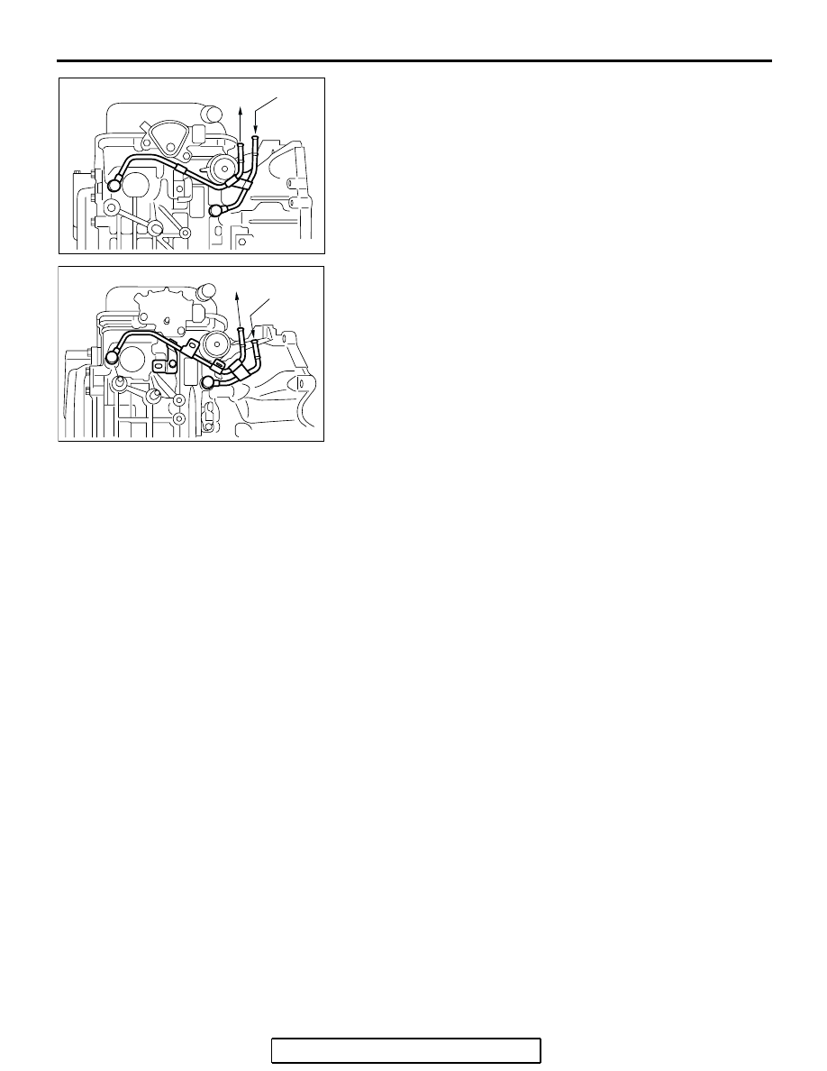
AC305868

AB

<F4A4B>

TO 
COOLER

FROM
COOLER

AC305869

AB

<F4A5A>

TO 
COOLER

FROM
COOLER

ON-VEHICLE SERVICE

TSB Revision

AUTOMATIC TRANSAXLE

23A-371

OIL COOLER FLOW CHECK

M1231013100214

After the new or repaired transaxle has been installed, fill to the 
proper level with DIAMOND ATF SP III. The flow should be 
checked using the following procedure:

CAUTION

With the fluid set at the proper level, transmission fluid 
collection should not exceed one quart or internal damage 
to the transaxle may occur.
1. Disconnect the OUTLET line (from cooler) at the transaxle 

and place a collecting container under the disconnected line.

2. Run the engine at curb idle speed with the shift selector in 

neutral.

3. If transmission fluid flow is intermittent or it takes more than 

20 seconds to collect one quart of transmission fluid, replace 
the cooler.

4. If flow is within acceptable limits, reconnect the cooler line. 

Then fill the transaxle to the proper level, using DIAMOND 
ATF SP III.

AC305868

AB

<F4A4B>

TO 
COOLER

FROM
COOLER

AC305869

AB

<F4A5A>

TO 
COOLER

FROM
COOLER

ON-VEHICLE SERVICE

TSB Revision

AUTOMATIC TRANSAXLE

23A-372

TRANSMISSION RANGE SWITCH CHECK

M1231021600106

NOTE: For vehicles with sport mode, four positions (P, R, N, D) 
are used.

TRANSMISSION RANGE SWITCH AND CONTROL 
CABLE ADJUSTMENT

M1231021700051

1. Set the selector lever to the "N" position.

TRANSMISSION 
RANGE

TERMINAL CONNECTION OF 
TESTER

SPECIFIED CONDITION

P

− 8, 9 − 10

Less than 2 ohms.

R

− 8

N

− 8, 9 − 10

D

− 8

3

− 8

2

− 8

L

− 8

AC305881

AC305532

AC305679

<F4A4B>

<F4A5A>

AC

TRANSMISSION
RANGE SWITCH

TRANSMISSION
RANGE SWITCH

AC210182

AC304078

AC306426

P

R

N

D

<F4A5A>

3

2

L

P

R

N

D

<F4A4B>

AB

ON-VEHICLE SERVICE

TSB Revision

AUTOMATIC TRANSAXLE

23A-373

2. Loosen the control cable to the manual control lever 

coupling nut to free the cable and lever.

3. Set the manual control lever to the neutral position.

4. Loosen the transmission range switch body mounting bolts 

and turn the park/neutral position switch body so the hole in 
the end of the manual control lever and the hole (section A 

− 

A in the figure on the left) in the flange of the transmission 
range switch body flange are aligned.
NOTE: The transmission range switch body can be aligned 
by inserting a 5-mm diameter steel bar into the end hole of 
the manual control lever and the flange hole of the transmis-
sion range switch body.

5. Tighten the transmission range switch body mounting bolts 

to the specified torque. Be careful at this time that the switch 
body does not move.

Tightening torque: 11 

± 1 Nm (96 ± 8 in-lb)

AC305881

AC305532

AC305679

ADJUSTING NUT

ADJUSTING NUT

TRANSAXLE
CONTROL CABLE

TRANSAXLE
CONTROL CABLE

MANUAL CONTROL LEVER

MANUAL CONTROL LEVER

AD

<F4A4B>

<F4A5A>

AC306319

<F4A4B>

11 ± 1 N·m
96 ± 8 in-lb

MOUNTING BOLTS

MANUAL
CONTROL
LEVER

<F4A5A>

11 ± 1 N·m
96 ± 8 in-lb

MOUNTING BOLTS

MANUAL
CONTROL
LEVER

SECTION A - A

HOLE IN END

HOLE IN
FLANGE

TRANSMISSION 
RANGE SWITCH BODY

MANUAL
CONTROL
LEVER

AB


Content   ..  571  572  573  574   ..