Mitsubishi Galant 9G. Manual - part 232


  Index      Mitsubishi     Mitsubishi Galant 9G - service repair manual


Search            


Content   ..  230  231  232  233   ..


Mitsubishi Galant 9G. Manual - part 232


GENERAL DESCRIPTION

TSB Revision

HEATER, AIR CONDITIONING AND VENTILATION

55A-4

OPERATION

.

CONDENSER  FAN AND RADIATOR  FAN 
CONTROL

The PCM judges the required revolution speed of 
radiator fan motor and condenser fan motor using 
the input signals transmitted from A/C switch, output 
shaft speed sensor and engine coolant temperature 
sensor. The PCM activates the fan control relays to 
drive the radiator fan motor and condenser fan 
motor.

.

COMPRESSOR CONTROL

When operating the air conditioning switch

• The air thermo sensor, which senses the temper-

ature of the air flowing out of the evaporator, 
deactivates the compressor at 3

°C (37.4°F) or 

below.

• The dual pressure switch turns OFF when the 

refrigerant pressure becomes excessively high or 
low, thus protecting the compressor circuit (See 
Table below).

• When the air thermo sensor is activated, and the 

ignition switch, blower switch, and air condition-
ing switch are ON, the A/C compressor clutch 
relay is energized.

When operating the mode selection dial

• The air conditioning will work when the mode 

selection dial is set to the "Defroster" or 
"Defroster/foot" position, or the temperature con-
trol dial is set to the "MAX A/C" position. In other 
dial positions, when the air conditioning switch is 
turned on, the air conditioning will work.

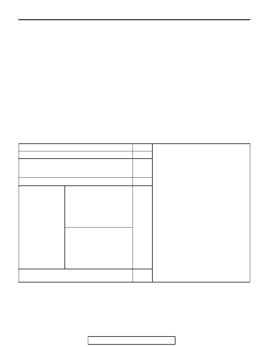
A/C Compressor Clutch Relay ON Conditions

Ignition switch (IG2)

ON

NOTE: A/C  compressor clutch relay is 
de-energized when any one switch, sensor 
or control unit shown on the left turns off.
NOTE:  The components marked by 

*


communicate with the PCM. If the air thermo 
sensor detects a temperature of 3

°

(37.4

°

F), the A/C-ECU will turn off the A/C 

compressor clutch relay.

Blower switch

ON

Air conditioning switch, mode selection dial 
defroster, defroster/foot position or temperature 
control MAX A/C

ON

Air thermo sensor

*

Pressure detected 
by A/C pressure 
sensor

2.94 MPa or less (If the 
refrigerant pressure exceeds 
2.94 MPa, A/C compressor 
clutch relay is not ON 
condition until the refrigerant 
pressure has been measured 
up to 235 MPa or less.)

ON

0.19 MPa or more (If the 
refrigerant pressure falls short 
of 0.19 MPa, A/C compressor 
clutch relay is not ON 
condition until the refrigerant 
pressure has been measured 
up to 0.22 MPa or more.)

A/C compressor clutch relay driving transistor (within 
powertrain control module)

ON

SERVICE PRECAUTIONS

TSB Revision

HEATER, AIR CONDITIONING AND VENTILATION

55A-5

SERVICE PRECAUTIONS

CAUTION LABELS

M1552017400097

The refrigerant gas warning label must be affixed in the location 
shown in the figure on the left. Follow the instructions on the 
label when servicing.

MANUAL A/C DIAGNOSIS

INTRODUCTION TO HEATER, AIR CONDITIONING AND VENTILATION DIAGNOSIS

M1552012200333

Air is drawn into the heater assembly from either the 
outside, or from the inside of the passenger cabin if 
DEFROST, maximum cooling or RECIRCULATION 
are selected. The air is then forced through the evap-
orator where heat is removed, cooling and de-humid-
ifying the air. Depending on the temperature 
selected, a portion of this air is then forced through 
the heater core to achieve the selected discharge 
temperature.

If the system does not cool properly, look for a prob-
lem with the refrigerant, blower or air distribution sys-
tems. If the system does not heat properly, look for a 
problem with the coolant, blower or air distribution 
systems. In either case all system fuses, circuit 
breaker and relays should be checked.

HEATER,  AIR  CONDITIONING AND VENTILATION DIAGNOSTIC  TROUBLESHOOTING 
STRATEGY

M1552009600386

Use these steps to plan your diagnostic strategy. If 
you follow them carefully, you will be sure that you 
have exhausted most of the possible ways to find a 
heater, air conditioning and ventilation fault.
1. Gather information from the customer.

2. Verify that the condition described by the 

customer exists.

3. Find the malfunction by following the Symptom 

Chart.

4. Verify that the malfunction is eliminated.

No.

Contents

1

Name of air conditioner manufacturer

2

Amount of refrigerant

3

Name of compressor oil

4

Parts number

AC306336

AC306936

AB

AC200079

1

2

3

3

2

AB

4

MANUAL A/C DIAGNOSIS

TSB Revision

HEATER, AIR CONDITIONING AND VENTILATION

55A-6

DIAGNOSTIC FUNCTION

M1552019800035

HOW TO CONNECT THE SCAN TOOL (MUT-III)

Required Special Tool:

•  MB991958: Scan Tool (MUT-III Sub Assembly)

• MB991824: Vehicle Communication Interface (V.C.I.)

• MB991827: MUT-III USB Cable

• MB991910: MUT-III Main Harness A (Vehicles with CAN 

communication system)

CAUTION

To prevent damage to scan tool MB991958, always turn the 
ignition switch to the "LOCK" (OFF) position before con-
necting or disconnecting scan tool MB991958.
1. Ensure that the ignition switch is at the "LOCK" (OFF) 

position.

2. Start up the personal computer.
3. Connect special tool MB991827 to special tool MB991824 

and the personal computer.

4. Connect special tool MB991910 to special tool MB991824
5. Connect special tool MB991910 to the data link connector.
6. Turn the power switch of special tool MB991824 to the "ON" 

position.
NOTE: When the special tool MB991824 is energized, the 
special tool MB991824 indicator light will be illuminated in a 
green color.

7. Start the MUT-III system on the personal computer.
NOTE: Disconnecting the scan tool special tool MB991824 is 
the reverse of the connecting sequence, making sure that the 
ignition switch is at the "LOCK" (OFF) position.

HOW TO READ AND ERASE DIAGNOSTIC 
TROUBLE CODES

Required Special Tool:

•  MB991958: Scan Tool (MUT-III Sub Assembly)

• MB991824: Vehicle Communication Interface (V.C.I.)

• MB991827: MUT-III USB Cable

• MB991910: MUT-III Main Harness A (Vehicles with CAN 

communication system)

AC305412

AB

MB991910

DATA LINK

CONNECTOR

MB991824

MB991827

MANUAL A/C DIAGNOSIS

TSB Revision

HEATER, AIR CONDITIONING AND VENTILATION

55A-7

CAUTION

To prevent damage to scan tool MB991958, always turn the 
ignition switch to the "LOCK" (OFF) position before con-
necting or disconnecting scan tool MB991958.
NOTE: If the battery voltage is low, diagnostic trouble codes will 
not be output. Check the battery if scan tool MB991958 does 
not display.
1. Connect the scan tool MB991958 to the data link connector.
2. Turn the ignition switch to the "ON" position.
3. Select "Interactive Diagnosis" from the start-up screen.
4. Select "System Select."
5. Choose "Air Conditioner" from the "BODY" tab.
6. Select "MITSUBISHI."
7. Select "Diagnostic Trouble Code."
8. If a DTC is set, it is shown.
9. Choose "Erase DTC" to erase the DTC.

HOW TO READ DATA LIST

Required Special Tool:

•  MB991958: Scan Tool (MUT-III Sub Assembly)

• MB991824: Vehicle Communication Interface (V.C.I.)

• MB991827: MUT-III USB Cable

• MB991910: MUT-III Main Harness A (Vehicles with CAN 

communication system)

CAUTION

To prevent damage to scan tool MB991958, always turn the 
ignition switch to the "LOCK" (OFF) position before con-
necting or disconnecting scan tool MB991958.
1. Connect the scan tool MB991958 to the data link connector.
2. Turn the ignition switch to the "ON" position.
3. Select "Interactive Diagnosis" from the start-up screen.
4. Select "System Select."
5. Choose "Air Conditioner" from the "BODY" tab.
6. Select "MITSUBISHI."
7. Select "Data List."
8. Choose an appropriate item and select the "OK" button.

AC305412

AB

MB991910

DATA LINK

CONNECTOR

MB991824

MB991827

AC305412

AB

MB991910

DATA LINK

CONNECTOR

MB991824

MB991827


Content   ..  230  231  232  233   ..